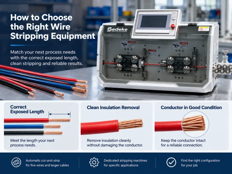


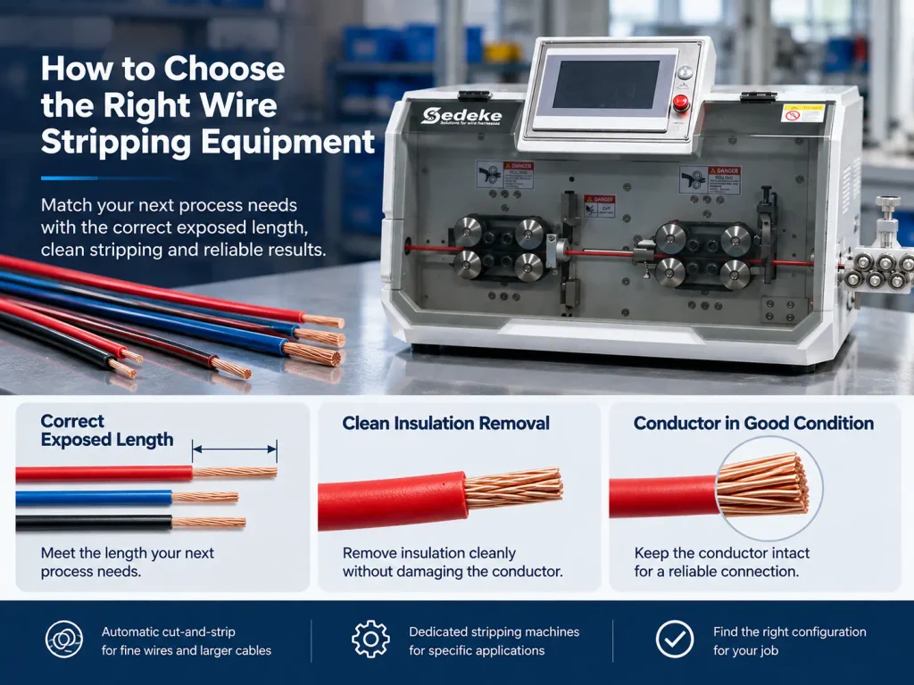
Choose stripping equipment around the wire end your next process needs: the correct exposed length, clean insulation removal and a conductor that meets the connection requirements. A small accuracy figure is useful only when it describes the feature you need to control.
If your line produces short strips, damaged strands or inconsistent results after a wire change, start by separating length control from cutting depth and material handling. That tells you which machine features deserve attention and what a sample run should demonstrate.
At Sedeke, we offer automatic cut-and-strip equipment for fine wires and larger cables, alongside dedicated stripping machines. This guide helps you narrow that choice and discuss the right configuration for your job.
What Does Wire Stripping Tolerance Measure?
Wire stripping tolerance is the permitted variation in a specified stripping dimension. For a fully stripped end, strip length runs from the insulation edge to the conductor tip, using the drawing’s reference points. It controls how much conductor is available for the next operation.
Keep these three dimensions separate when comparing equipment:
| Dimension | What you are controlling | Why it matters to your job |
|---|---|---|
| Strip length | Length of exposed conductor at each end | Preparation for the terminal, connector or next assembly step |
| Insulation cutting depth | How far the blade enters the insulation | Removing insulation while protecting the material beneath it |
| Overall cut length | Finished length of the wire | Fit within the harness or assembly |
A machine’s cut-length accuracy describes the third row. Use strip-length results and conductor inspection to evaluate the first two. For multilayer cable, specify each jacket, shield and inner-insulation preparation separately.
Start with the Terminal Requirement
Use the terminal or assembly drawing to set your strip-length target. The wire end needs to fit the connection it will enter. Too little exposed conductor can interfere with the intended preparation; too much can leave more exposed wire than the assembly allows.
Check the relevant terminal specification for the length and conductor-condition requirements. For example, TE Connectivity’s Cluster Block application specification provides preparation requirements for its covered contacts in section 3.2 and the associated figures.
For a worked example, a requirement of 6.0 ±0.2 mm gives an acceptable dimensional window of 5.8–6.2 mm. Both ends need their own entry if they use different terminals or strip lengths.
Bring that finished requirement into your equipment comparison. It lets you compare suppliers on the same job instead of paying attention to an accuracy number for a different dimension.
Match the Accuracy Problem to the Right Machine Feature
Different defects call for different checks. Use the result on the wire to decide whether to prioritize length control, tooling or feeding.
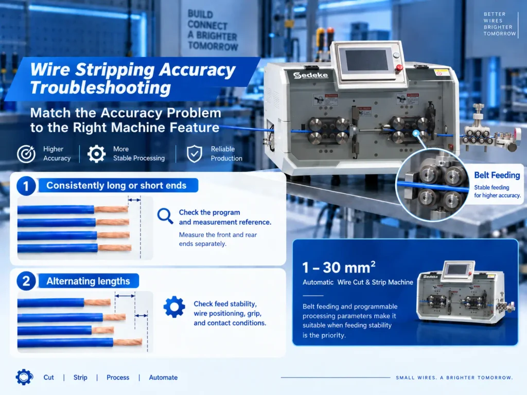
Consistently long or short ends: check the program and reference
When cleanly stripped ends cluster on the same side of the target, first compare the programmed length with the drawing and measurement reference. Check the front and rear ends separately. A repeatable offset calls for a different investigation from a sequence of random long and short strips.
After an approved setup correction, measure fresh pieces under the same conditions. Keep the original results so you can see whether the correction moved the output toward the target.
Alternating lengths: look at feed stability
When results scatter, examine wire positioning and grip before repeatedly changing the length setting. Wire slip, an inconsistent feed path or unsuitable contact conditions can undermine repeatable positioning.
For soft or surface-sensitive insulation, compare grip and surface condition together. More pressure can mark or deform the material; too little grip can let it slip. Our belt and roller feeding guide explains how to compare these arrangements for your material.
For 1–30 mm² wires, consider our ESC-BX30 when feeding is a priority in your cut-and-strip job. Its belt feed and programmable processing parameters give us a starting point for discussing how to handle your material.
Residual insulation or damaged strands: examine the cutting and removal sequence
Blade stripping combines an insulation cut with a pull-off movement. An incomplete cut can leave insulation attached. A cut that reaches the conductor can nick strands. If a cut sleeve remains on the wire, examine the removal step as well as the cut; simply cutting deeper does not address every residue problem.
Check whether the job calls for full or partial stripping, whether the tooling suits the wire construction, and where any conductor damage appears. Hold damaged output for quality review. Trained personnel should follow the machine’s isolation and setup instructions before accessing or adjusting tooling.
For an existing machine with recurring faults, use our wire stripping troubleshooting guide for the detailed checks. For a new purchase, make clean removal and conductor condition part of the sample comparison.
A Correct Average Can Still Hide Unacceptable Output
The following illustrative readings use the 5.8–6.2 mm window above:
| Sample pattern | Individual strip lengths, mm | What to do next |
|---|---|---|
| Consistent offset | 6.3, 6.4, 6.3, 6.4, 6.3 | All five are too long. Check the length program and reference before investigating compensation |
| Wide variation | 5.6, 6.0, 6.4, 5.7, 6.3 | The average is 6.0, but four pieces fail. Investigate the source of variation |
The second group spans 0.8 mm, twice the 0.4 mm allowed window. Moving all readings by the same amount will not make that spread fit. You need to reduce the variation before centering the result can solve the problem.
This distinction between process position and spread is also part of NIST’s process capability guidance. Use individual results to diagnose the pattern, then apply your production sampling plan to evaluate the corrected process. Five illustrative readings are a teaching example, not a production acceptance plan.
Choose a Sedeke Configuration for the Actual Wire
Your wire construction and preparation sequence should lead the shortlist. Conductor size alone leaves out insulation behavior, outside diameter and the layers you need to remove.
For fine, short single-conductor jobs, start with our ESC-BX6 wire cutting and stripping machine. Its wire range is AWG 32–20, with a stripping-length range of 0.1–30 mm and roller feeding. It is a relevant starting point when your job combines fine wire with short end preparation. Match the actual insulation and finished dimensions during the application review.
For larger wires, consider our ESC-BX30 automatic cutting and stripping machine. Its 1–30 mm² range and belt feeding address a different job from the fine-wire model. For special cable requirements, send a sample so we can evaluate the application and discuss the configuration.
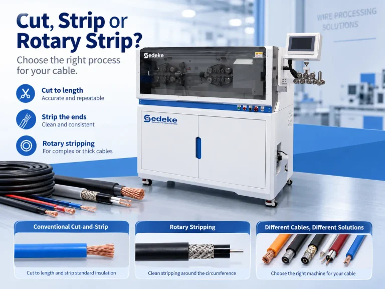
For coaxial or multilayer end preparation, start with our dedicated wire stripping machines. Choose around the required layer sequence and retained material. A machine that handles a single insulation strip does not automatically cover a stepped jacket, shield and dielectric preparation.
Match the final configuration to the complete wire end and the rate you need to run.
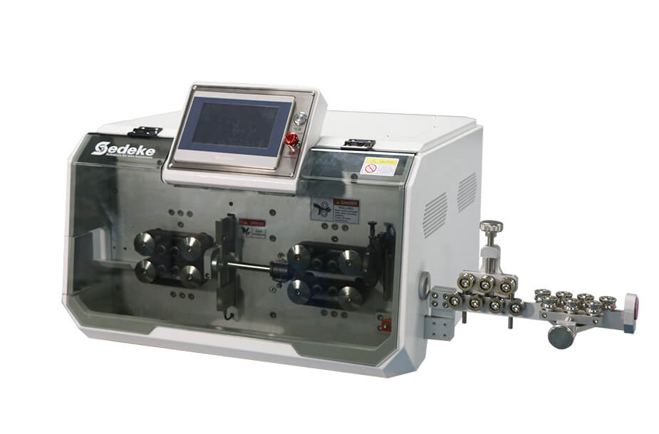
Make the Sample Run Answer Your Purchasing Question
Use actual production wire and the intended end geometry. Include more than one wire when different constructions place different demands on the process.
For a useful comparison, ask the trial to answer:
- Does each end meet its length limits? Retain individual measurements rather than only an average.
- Is the insulation removed as intended? Distinguish full stripping from an intentionally retained sleeve.
- Does the conductor meet the connection requirements? Check its condition separately from length.
- Does the result hold at the proposed operating rate? Include relevant restart or material-change conditions in the agreed trial.
If measurements disagree, first remeasure the same identified sample with consistent support and reference points. Resolve the measurement method before attributing the difference to the machine.
Use the same trial scope when comparing quotations: machine, tooling, feeding arrangement, wire preparation and required output. You can then compare what each quotation includes for your job.
FAQ
Does a 0.01 mm setting increment mean ±0.01 mm stripping accuracy?
No. The setting increment is the smallest change you can enter. Finished-wire accuracy also involves positioning, material handling, tooling and the measurement method. Compare the relevant processed dimension with your required limits; do not use a programming increment as the finished-part tolerance.
How should I specify a partial strip?
Show the insulation cut position and where the retained sleeve should sit after processing. State that the sleeve is intentional. This lets the trial check both the strip geometry and the retained insulation instead of treating every remaining sleeve as an incomplete strip.
Can one setup handle different wires with the same AWG?
Do not select the setup from AWG alone. Wires with the same conductor size can have different insulation thicknesses, outside diameters and constructions. Keep the wire part number with the job settings, and check the new material before carrying an accepted setup across to it.
Should I order a tighter tolerance than my drawing requires?
Set the purchasing target around the finished connection and the consistency your process needs. If you want additional margin, discuss it as a separate requirement so the supplier can quote and test that scope. A smaller number for the wrong dimension adds no useful information to the comparison.
What should I send if I do not have a full technical drawing?
Start with a wire photo, the wire size or part number, and the strip length you need. Include the terminal reference if you have it. We can use those details to begin the equipment discussion and identify the sample information needed for the next step.
Find the Right Starting Point for Your Application
If you are adding a new wire or replacing equipment that struggles with the current job, start with the wire and the result you need.
Send Sedeke a wire photo and your required strip length. We can help you narrow the machine choice and discuss sample processing. Add your target output and required delivery date when you are ready for a current quotation.