

Quick answer
Belt feeding is often worth testing when you need a longer contact area around a soft, smooth, flexible, or surface-sensitive material. Roller feeding can be a practical choice when your material has a stable profile and the rollers can grip it without slipping, flattening, or leaving unacceptable marks. Neither system is automatically more accurate or faster. You should compare them with the same material, cutting length, payout condition, batch size, and quality criteria. In Sedeke’s cutting-machine range, the EC-6500 uses belt feeding and the EC-6800 uses roller feeding.
A more useful comparison is whether each system moves your material consistently while preserving its shape and surface.
What the feeding system actually controls
The feeding system grips your material and advances it toward the cutting unit. It helps determine whether the machine presents the expected length and whether the material stays aligned as it moves. It does not create the cut by itself.
A cut can be wrong even when the feeder works correctly. Blade condition, guides, cutting timing, material payout, straightening, control settings, and the material itself can all affect the result. A sharp blade cannot correct a feed system that allows the material to slip or deform.
When you compare belt feeding with roller feeding, separate the result into four questions:
- Does the material advance by the programmed amount?
- Does it stay centered and maintain its profile?
- Does the feed contact leave acceptable surface conditions?
- Does the result remain stable through a consecutive production run?
This prevents you from choosing a machine based on one catalogue feature while missing the actual cause of variation.
How belt feeding and roller feeding differ
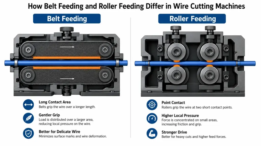
Belt and roller systems both use friction to move material, but they apply that contact differently.
Belt feeding
A belt-feed system contacts the material across a longer section of the feed path. That extended contact can spread the gripping force and give the system more surface over which to develop traction. This is why belt feeding is commonly considered for smooth cable, flexible tubing, soft jackets, or profiles that are difficult to hold with a short contact zone.
You still need to control the setup. Too much belt pressure can flatten soft material. A worn, dirty, misaligned, or poorly tracked belt can cause marks, drift, or inconsistent movement. A seam or damaged area may also create a repeating defect. “Belt feeding” describes the mechanism, not a guaranteed result.
Roller feeding
A roller-feed system moves material through paired rotating rollers. Its contact is normally concentrated into shorter zones, and the grip depends on roller geometry, surface condition, pressure, alignment, and how well the material fits the path.
This can work well when your wire, strip, tube, or other stock has a consistent profile and can tolerate the required contact pressure. Roller feeding may also provide a direct, simple path for materials that remain dimensionally stable. But an incorrect roller profile or excessive nip pressure can mark, pinch, flatten, or steer the material. Low pressure can allow slip.
The correct pressure is therefore not “as high as possible.” It is the lowest stable setting that advances the material without unacceptable slip, deformation, or marking under the intended production conditions.
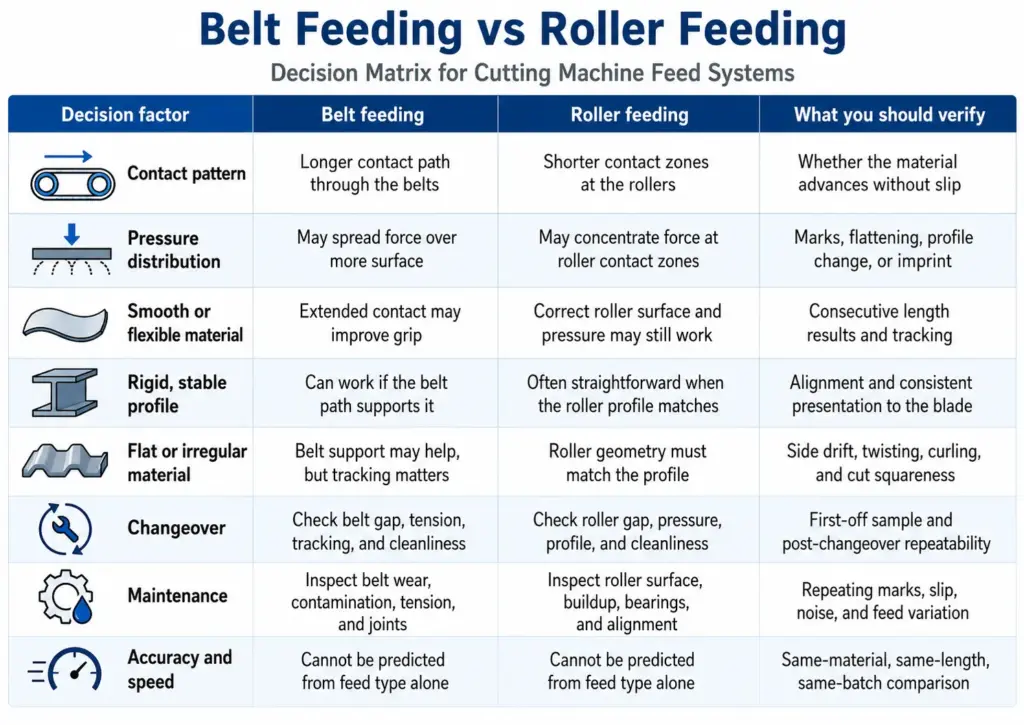
Belt feeding vs. roller feeding comparison
Use this table as a trial-planning guide, not as a universal ranking.
| Decision factor | Belt feeding | Roller feeding | What you should verify |
|---|---|---|---|
| Contact pattern | Longer contact path through the belts | Shorter contact zones at the rollers | Whether the material advances without slip |
| Pressure distribution | May spread force over more surface | May concentrate force at roller contact zones | Marks, flattening, profile change, or imprint |
| Smooth or flexible material | Extended contact may improve grip | Correct roller surface and pressure may still work | Consecutive length results and tracking |
| Rigid, stable profile | Can work if the belt path supports it | Often straightforward when the roller profile matches | Alignment and consistent presentation to the blade |
| Flat or irregular material | Belt support may help, but tracking matters | Roller geometry must match the profile | Side drift, twisting, curling, and cut squareness |
| Changeover | Check belt gap, tension, tracking, and cleanliness | Check roller gap, pressure, profile, and cleanliness | First-off sample and post-changeover repeatability |
| Maintenance | Inspect belt wear, contamination, tension, and joints | Inspect roller surface, buildup, bearings, and alignment | Repeating marks, slip, noise, and feed variation |
| Accuracy and speed | Cannot be predicted from feed type alone | Cannot be predicted from feed type alone | Same-material, same-length, same-batch comparison |
Choose by material and production condition
Soft or easily deformed material
If your tube or jacket changes shape under pressure, start by defining how much deformation is acceptable. Belt feeding may spread the load, but it can still compress the profile if the gap or tension is wrong. Roller feeding may work when the roller geometry supports the profile and the pressure is carefully controlled.
Inspect the material before and after feeding, not only after cutting. A round tube that becomes slightly oval may still reach the blade, yet fail a later assembly or sealing requirement.
Smooth, slippery, or surface-sensitive material
When the surface offers limited friction or cannot tolerate visible marks, compare traction and appearance together. More grip is not useful if it damages the surface. Lower pressure is not useful if it creates length variation.
Run multiple pieces and look for patterns. A mark at a regular interval may point to a belt joint, roller defect, contamination, or another repeating contact point. Random drift may point to payout tension, alignment, or inconsistent material geometry.
Rigid or dimensionally stable material
Stable profiles may be easier to guide through a roller system because they resist local deformation. That does not make roller feeding the automatic choice. Confirm that the roller path supports the actual width or diameter and that the stock does not rotate, skid, or walk sideways.
For rigid stock, also inspect the relationship between feeding and cutting. A stable feed can still produce a poor edge if the blade, clearance, or support is wrong.
Flat, irregular, or mixed-profile material
Flat strip, braided material, film, and non-round profiles can behave differently from round wire or tube. They may curl, twist, fold, or track toward one side. The feed path must control that movement without creating a new defect.
Do not choose from the material name alone. Two products called “silicone tube,” for example, can differ in hardness, wall thickness, surface finish, and reel set. Use the actual production material for the trial.
Frequent changeovers and short batches
When you change materials often, setup repeatability may matter more than peak cycle speed. Record the feed gap or pressure, guide selection, blade setup, payout arrangement, and inspection result for each approved material.
Then test whether an operator can restore the result after a restart or changeover. A system that produces one good sample but cannot reproduce it is not ready for mixed production.
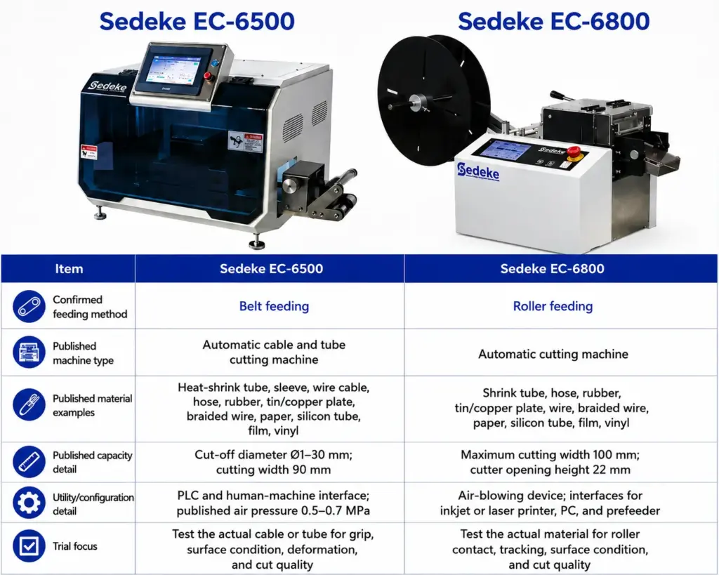
Sedeke EC-6500 vs. EC-6800
Within Sedeke’s cutting machine range, the EC-6500 and EC-6800 provide two relevant examples for this decision. The EC-6500 uses belt feeding, while the EC-6800 uses roller feeding. Their official pages also show that the machines differ in configuration and published scope, so you should not treat the comparison as feed type alone.
| Item | Sedeke EC-6500 | Sedeke EC-6800 |
|---|---|---|
| Confirmed feeding method | Belt feeding | Roller feeding |
| Published machine type | Automatic cable and tube cutting machine | Automatic cutting machine |
| Published material examples | Heat-shrink tube, sleeve, wire cable, hose, rubber, tin/copper plate, braided wire, paper, silicon tube, film, vinyl | Shrink tube, hose, rubber, tin/copper plate, wire, braided wire, paper, silicon tube, film, vinyl |
| Published capacity detail | Cut-off diameter Ø1–30 mm; cutting width 90 mm | Maximum cutting width 100 mm; cutter opening height 22 mm |
| Utility/configuration detail | PLC and human-machine interface; published air pressure 0.5–0.7 MPa | Air-blowing device; interfaces for inkjet or laser printer, PC, and prefeeder |
| Trial focus | Test the actual cable or tube for grip, surface condition, deformation, and cut quality | Test the actual material for roller contact, tracking, surface condition, and cut quality |
The Sedeke EC-6500 product page and EC-6800 product page support the published product scopes and specifications above. The feeding-method mapping comes from confirmed Sedeke product information.
Do not use the published speed fields to declare a winner. The available pages do not provide a safe, like-for-like test condition for comparing output. Your useful measure is accepted pieces per unit of time with the same material, length, payout, and inspection rules.
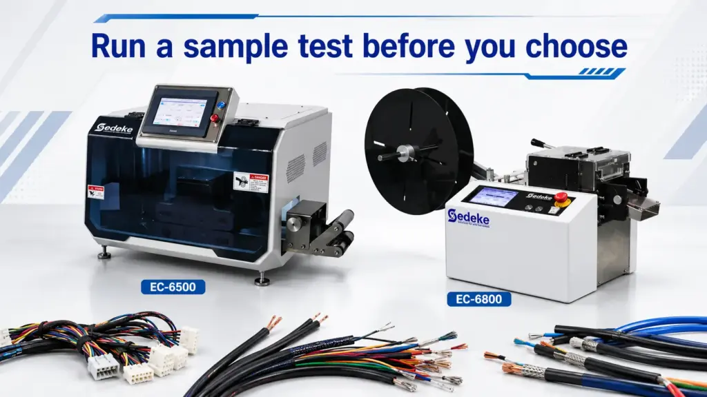
Run a sample test before you choose
Use five steps to approve the material and setup.
- Record the actual material. Note material type, profile, dimensions, hardness or stiffness if known, surface requirement, reel condition, and batch variation.
- Define acceptance criteria. Use your drawing or internal quality requirement for length, cut edge, deformation, surface marks, and allowable stoppages.
- Set up the complete feed path. Include payout, straightening, guides, feeder gap or pressure, and the cutting setup. A bench sample without production payout may hide a problem.
- Run consecutive pieces. One good cut is not enough. Use a quantity that can reveal repeating marks, drift, slip, jams, or heat buildup under your process conditions.
- Repeat after a stop or changeover. Record the setup and check whether the result returns without trial-and-error adjustment.
If either system needs excessive pressure to prevent slip, stop and investigate the whole path. The cause may be payout resistance, poor alignment, unsuitable guides, contamination, or a mismatch between the feed surface and material. Increasing pressure can hide the cause while creating deformation or marks.
Common decision mistakes
Avoid these shortcuts when comparing a belt feeding cutting machine with a roller feeding cutting machine:
- Choosing by the feed label without inspecting the actual material.
- Comparing catalogue speeds measured with different lengths or conditions.
- Blaming the feeder for defects caused by payout, guides, blade condition, or cutting setup.
- Approving the machine after a single good sample.
- Checking length but ignoring surface marks, profile change, tracking, or cut squareness.
- Assuming that a broader published material list guarantees every grade and dimension will run correctly.
Frequently asked questions
Is belt feeding better than roller feeding for soft tubing?
Belt feeding may be a better starting point when your tubing deforms under concentrated pressure because the belt contacts a longer section of the material. That does not guarantee a clean result. You still need to test belt pressure, tracking, surface marks, length consistency, and the cut edge with your actual tubing.
Does a belt-feed cutting machine leave no marks?
You should not assume that. A belt can distribute feed force across a larger area, but excessive tension, dirt, worn belt surfaces, seams, or poor alignment can still mark or deform the material. Define an acceptable surface condition and inspect a consecutive sample run before approving the setup.
Can roller feeding be used for cables and tubes?
Yes, when the roller profile, pressure, material stiffness, and feed path suit the application. Roller feeding is not automatically limited to rigid materials. You need to check whether the material slips, flattens, twists, or receives local pressure marks under the production setup.
Is belt feeding more accurate than roller feeding?
Feed type alone does not determine cutting accuracy. Length consistency also depends on drive control, slip, material payout, straightening, guides, cutting timing, setup, and maintenance. Compare both machines under the same material, cut length, quantity, and inspection method rather than comparing unrelated catalogue claims.
How should you compare cutting speed between two feed systems?
Use the same material, programmed length, batch size, upstream payout, and acceptance criteria. Record good pieces per unit of time, not just mechanical cycles. Include stops, jams, rework, and changeover time. Published speeds are not comparable when manufacturers use different lengths or test conditions.
Can one automatic cutting machine process many materials?
It may process a broad material range, but each material still needs its own verified setup. Diameter or width alone is not enough. Record profile, stiffness, surface finish, reel condition, required cut quality, feed pressure, guides, and any upstream support before releasing a new recipe.
What should you inspect during a material sample test?
Check cut length consistency, squareness, burrs or crushed edges, surface marks, deformation, tracking, slip, jams, and repeatability after a stop or changeover. Use your drawing or internal quality requirement for numeric limits. Do not copy a tolerance from an unrelated material or machine trial.
What is the main difference between Sedeke EC-6500 and EC-6800?
The confirmed feed-system difference is that the EC-6500 uses belt feeding and the EC-6800 uses roller feeding. Their published equipment scopes and features also differ. You should compare your material dimensions, shape, surface requirement, utilities, peripheral needs, and trial results before selecting either model.
What maintenance points differ between belts and rollers?
For belts, inspect wear, contamination, tracking, tension, joints, and matching upper and lower movement. For rollers, inspect surface wear, buildup, profile condition, alignment, pressure, and bearing movement. For both systems, clean the feed path and confirm the setting after maintenance before resuming a production batch.
Do you need a prefeeder with an automatic cutting machine?
You may need one when the machine must pull material from a heavy reel, overcome inconsistent payout tension, or handle long and flexible stock. A prefeeder should support stable delivery without pushing or pulling against the machine’s measuring system. Confirm compatibility, control signals, and the actual reel condition during the trial.
Final thoughts
Choose the feed system that moves your actual material consistently without unacceptable slip, marking, deformation, or tracking errors. Belt feeding gives you a longer contact path; roller feeding gives you direct roller contact. Those differences guide the trial, but they do not replace it.
For a Sedeke comparison, shortlist the belt-fed EC-6500 and roller-fed EC-6800 against your material dimensions, utilities, peripheral needs, and acceptance criteria. Then test the real production material and compare accepted output under the same conditions.