

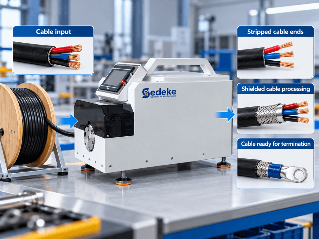
Choose railway cable processing equipment by the finished cable end you need and the condition in which the cable reaches the station. Thin-wall control wire, shielded cable and power cable can require different preparation routes within the same harness order.
For reel-fed wire with repeated cut lengths, start with a cut-and-strip route. For cable already cut to length, compare a separate end-stripping station. If the drawing calls for shield trimming, folding or another termination operation, include that work explicitly in the equipment scope.
The useful purchasing output is a station plan: which cable family runs where, what each station delivers and what must pass inspection before the next operation. Here is how to build one.

Separate railway cable families before comparing machines
Two railway cables can need different operations even when both have a single conductor.
For example, OMERIN’s VARPREN RW EN 50306-2 cable has a flexible tinned-copper conductor and thin-wall insulation. TE’s EN 50306-3 cable adds screening and a thin-wall sheath around a single-core construction. The second cable introduces separate sheath and screen requirements before you reach the conductor insulation.
Group your cable list by construction and required end preparation. Keep the cable manufacturer’s part number and drawing revision with each group.
| Cable family or incoming condition | First equipment route to compare | What the quotation must distinguish |
|---|---|---|
| Single-core wire supplied on a reel | Automatic cutting and stripping | Finished length, End A and End B preparation, identification and collection |
| Shielded cable requiring stepped end preparation | Cutting plus defined layer-processing operations, or a separate end-processing station | Jacket removal, screen treatment and inner-insulation removal |
| Jacketed multicore cable | Jacket preparation followed by the required individual-core operations | Which cores need processing, their end lengths and whether they remain accessible |
| Power cable already cut to length | A dedicated end-stripping station plus the specified lug-termination operation | Cable support, grip, strip geometry and terminal/tooling combination |
Use this table to allocate work. A cable family name alone cannot confirm that a particular machine will complete every operation.
Record outside diameter as well as conductor cross-section. Then add the insulation or jacket material, both end drawings and the incoming form: reel, loose coil or pre-cut length. Those details let you compare machines against the same job.
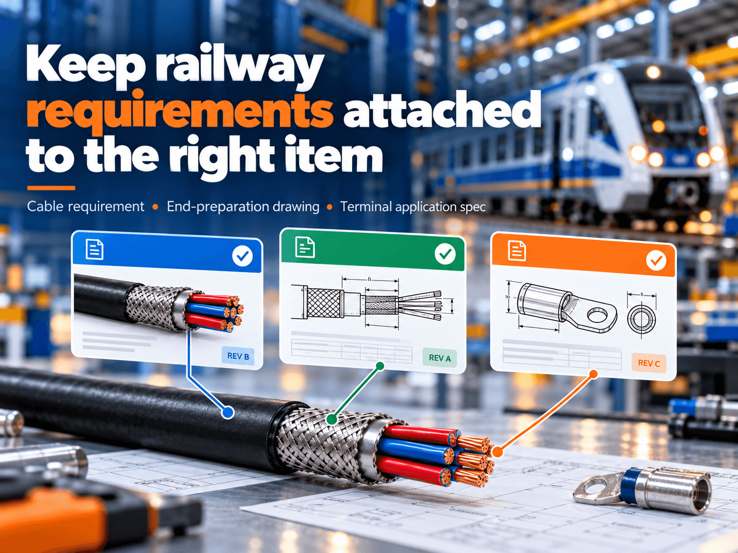
Keep railway requirements attached to the right item
For a European project, obtain the applicable requirements from the approved cable list, drawings and contract before you prepare the machine enquiry.
BS EN 45545-2:2020+A1:2023 addresses fire behaviour of railway-vehicle materials and components. Buying a stripping machine does not establish that compliance.
Keep three references separate in your station plan:
- The cable or material requirement identifies the approved incoming item.
- The end-preparation drawing defines what you remove and what must remain.
- The terminal application specification defines the connection and its processing requirements.
For each operation, record the document and revision that supply its acceptance limits. If the cable is approved but the required screen exposure is undefined, resolve the end drawing before approving that operation. A standard name alone does not supply a blade setting.
Diagnose stripping problems before choosing a larger machine
A cable that fits the machine’s diameter range can still produce an unacceptable end. For thin-wall insulation, check the space between the intended cut and the conductor. For a jacketed cable, inspect the underlying screen or cores. “Halogen-free” describes a material characteristic; it does not specify wall thickness, adhesion or a transferable stripping recipe.
Separate the cutting action from the removal action during your trial. Inspect the end after the cut, then again after the insulation or jacket has been pulled away. This helps you establish when damage appears before changing settings.
As a general processing reference, ZVEI’s cable application notes, sections 4.3–4.6, distinguish roller pressure, gripping force, blade geometry and stripping depth. They caution against slipping, deformation and damage to underlying cable structures. These are automotive cable notes, not railway acceptance criteria; use your railway cable and termination documents for the actual limits.
The following diagnostic sequence is a trial-planning recommendation. The observations suggest checks, not a proven cause.
| Observation during the trial | What to investigate first | Decision before continuing |
|---|---|---|
| A conductor or retained layer is marked at the cut position | Blade depth, centring, blade condition and actual cable dimensions | Hold affected samples; establish a cut that preserves the retained layer |
| The cut looks acceptable, but damage appears during removal | The removal movement, grip and whether the cut has separated the intended material | Evaluate the removal step separately rather than simply deepening the cut |
| End length changes between pieces | Cable movement at the grip, feed consistency and the measurement reference | Stabilise positioning, then repeat the dimensional check |
| One cable lot works and another does not | Incoming dimensions, construction and condition against the approved sample | Determine whether the existing recipe still applies before releasing that lot |
Record the change and its result. If you alter blade depth, grip and removal movement together, a good sample will not tell you which adjustment solved the problem. A repeatable process needs more than one visually clean end.
Decide where cutting ends and end preparation begins
If you need repeated lengths from a reel, our wire cutting and stripping equipment is the starting point for a configuration review. Include both cable ends and the required collection method in that review so the quotation covers the work delivered to your next station.
If your cables already arrive cut, a separate stripper lets you evaluate end preparation while retaining the existing cutting route. At Sedeke, our CS series rotary cable stripping machines include the CS-100, with a stripping diameter of 5 to 25 mm and a stripping length of 0 to 100 mm, and the CS-300, with corresponding ranges of 12 to 50 mm and 0 to 300 mm.
Use those ranges for an initial shortlist. The trial must still match the cable construction, required removal and material you need to retain. Larger cable size alone does not determine the cutting method; our rotary versus standard wire stripping guide explains that choice.
For shielded cable, write down the screen operation separately. Removing a jacket, shortening a braid and folding the braid back are different tasks. Ask the supplier to identify which are included in the proposed configuration and which need another station.
Specify shielded, coaxial and multicore ends layer by layer
For a screened end, draw the jacket edge, screen end and inner-insulation edge separately. Give End A and End B their own dimensions when the connections differ. “Strip 40 mm,” for example, is incomplete if it does not identify which layer the dimension describes. That number is only an illustration, not a recommended strip length.
Then define the screen’s finished condition: retained in place, trimmed, folded back or prepared for a particular shield connection. A jacket stripper can expose the braid successfully while leaving this operation unfinished. Compare quotations against the end that the connector assembly station actually needs.
For coaxial cable, include the connector supplier’s preparation drawing in the enquiry. The centre conductor, dielectric and outer conductor have separate preparation requirements. A machine’s programmable step count does not by itself show that it can produce the required geometry without damaging the retained layers.
For a twisted-pair or multicore assembly, identify how far the jacket must be removed and how much core separation or untwisting the assembly permits. Leave those limits to the cable/connector design; there is no universal exposed length suitable for all communication cables. Include any required electrical performance verification in the assembly test plan rather than judging the connection only from a photograph.
During the trial, check whether the operator can reach each core without pulling on the others and whether the prepared end remains suitable for connector assembly. If manual screen work is still required, time that work and identify the tool and inspection step in the quotation.
Plan heavy-cable handling with the termination station
For long power cables, evaluate the supported cable as well as the end inside the machine. Record the cable’s outside diameter, mass per metre, length, supply format and permitted handling conditions. Cross-section alone cannot establish its stiffness, required support or suitability for a coiler.
Run the handling trial at the intended production length. A short offcut can demonstrate stripping while concealing the loading and repositioning work required for the complete cable. Observe how the operator presents the first end, reaches the second end and transfers the cable to the lug-crimping station.
Make the receiving method serve that next operation. If both ends immediately need lug preparation, a supported layout that keeps them accessible may save an uncoiling step. If the cable must move to another area, a controlled coil may be more practical. Check the cable supplier’s permitted bend conditions before choosing the receiving diameter. Our guide to handling long cables after cutting and stripping compares stacking, coiling and spooling in more detail.
For the crimping station, confirm the lug, conductor and approved die combination before selecting press capacity. Also check loading clearance and cable support in the proposed arrangement. A press with adequate force can still be awkward to use if the cable cannot be positioned or the finished lug cannot be removed without disturbing the workpiece.
Define the output of every station
Make the handoff explicit before comparing prices. A stripper’s output might be a cable with exposed screen, while the next station needs a screen trimmed and prepared for termination. Both descriptions can be correct, but they represent different amounts of completed work.
Use a short station sheet like this:
| Station | Input | Required output | Release check |
|---|---|---|---|
| Cut and identify | Approved cable and released cut list | Correct length associated with its wire or cable ID | Length and identification match the job |
| Strip jacket or insulation | Identified cable with End A/B requirements | Specified material removed; required layers retained | Dimensions and retained-material condition meet the drawing |
| Prepare screen, where required | Cable with exposed screen | Screen geometry ready for the specified connection | Required length and treatment match the termination drawing |
| Terminate | Prepared end, specified terminal and tooling | Connection ready for the next assembly operation | Checks required by the terminal specification and quality plan |
| Collect and hand over | Accepted processed pieces | Identifiable pieces or kits in the required receiving format | Quantity, identity, end condition and inspection status are retained |
The release check should name a measurement or observation and its acceptance source. Avoid a generic “quality OK” box.
For crimped connections, retrieve the documents for the actual terminal and tooling. For example, Molex’s application-tooling guidance directs users to the relevant tooling documentation for crimp height, pull force and strip length. Apply the requirements for your selected connection rather than copying limits from a different terminal.
Give each crimp check a specific job
Crimp dimensions and pull testing answer different questions. The specified dimensional check assesses the formed connection; a pull test assesses mechanical retention under the prescribed test conditions. Neither should be replaced by a visual “looks tight” judgement. Molex distinguishes the checks for open- and closed-barrel connections and identifies damaged strands, mismatched components and tooling problems among possible reasons for poor pull-test results in its guidance linked above.
Use that distinction when investigating a failed sample: inspect the stripped conductor and verify the component/tooling combination before changing the press setting. Take the acceptance values from the applicable terminal documents, including the test method and treatment of insulation support.
If you request crimp-force monitoring, include a demonstration of the proposed system’s detection and rejection behaviour for your application. Ask how its limits are established and what happens to a rejected part. An alarm record should identify the affected piece or batch; a saved machine recipe alone does not establish this association. Keep the checks required by your quality plan even when monitoring is installed.
IEC 61373:2026 addresses shock and vibration tests for railway-vehicle equipment. It does not supply a universal crimp-height or pull-force limit for your terminal. Keep project-level validation and production connection checks as separate requirements, using the editions specified by the contract.
Arrange identification, protection and final testing in the assembly sequence
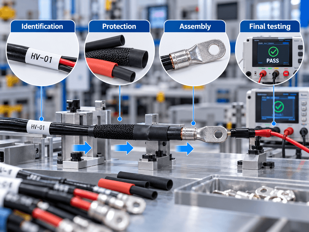
Check when sleeves, seals or other protective parts must be fitted. If a sleeve cannot pass over the completed lug, it needs to enter the sequence before that lug is attached. Show this dependency on the work instruction so it is included in the equipment and labour comparison.
Try the proposed identification method through the actual downstream operations. Confirm that the required ID remains readable, accessible and associated with the correct cable after protection, collection and assembly. Specify its content and position as well as the marking method.
For the finished assembly, define which tests the customer requires and verify that the proposed test setup supports them. A continuity result checks the defined electrical path; it does not replace the mechanical checks on a crimp. Record the assembly identity, test-program revision and result together so a failed assembly can be traced to the relevant production records.
Use a sample trial to expose unfinished work
Agree on the trial’s output before the machine runs. Include the complete sequence being quoted, the handling between operations and the checks required by your quality plan. Keep unfinished or rejected pieces out of the accepted count.
The following is an illustrative planning example, not a customer project or machine performance test.
A railway harness order contains a thin-wall control wire and a screened single-core cable. The screened cable needs different preparation at End A and End B.
| Trial observation | Purchasing decision |
|---|---|
| The control wire meets its cut-length and end-preparation requirements | Keep that configuration on the shortlist for this wire family |
| The screened cable’s jacket is removed correctly, but the required screen treatment remains unfinished | Record jacket stripping as completed; add screen preparation to the quoted route |
| End A passes, but End B has damage outside the drawing’s acceptance limits | Hold the cable from release; investigate the End B process and repeat the affected evaluation |
| Both ends pass, but identification is lost during collection | Revise the collection or identification step and repeat the handoff check |
This separates a successful operation from a finished, usable part. It also prevents you from comparing a fast jacket-only cycle with a slower route that completes the required screen and conductor preparation.
For each trial, keep one record containing:
- Cable part number, lot and drawing revision.
- End A and End B requirements, including retained layers.
- Machine configuration, tooling and recipe revision.
- Check method, acceptance source and recorded result.
- Unfinished operations, rejected pieces and disposition.
- Identity and condition of the pieces handed to the next station.
A photograph helps explain end geometry, but dimensional checks still need the method specified in the inspection plan. If an acceptance requirement is missing, record it as unresolved and settle it before production release.
Compare quotations at the same handoff point
Ask each supplier to quote the same output condition. State whether the price covers only jacket stripping, complete end preparation or a terminated cable ready for assembly. List the tooling, guides, supports and any separate operations included.
During the trial, measure accepted pieces reaching that handoff point over the full agreed elapsed time. Include the transfers and operator handling required by the proposed route. For mixed batches, record changeover and first-piece approval separately.
For example, a proposal that leaves screen trimming to an operator needs that operation included in its time and labour comparison. Otherwise, its apparent speed advantage describes a smaller job.
Estimate accepted output using the complete route
For a single operator completing the operations sequentially, use this planning calculation:
Accepted cables = available processing seconds ÷ complete seconds per cable × first-pass yield.
The following numbers are assumptions to illustrate the comparison, not Sedeke machine specifications or measured results. Assume a shift has 420 minutes available before job changeovers and first-piece approval. The complete route takes 50 seconds per cable, including both ends, screen work where needed and handling. Assume a 95% first-pass yield.
| Planning case | Changeover and first-piece time | Processing time left | Calculated accepted cables, rounded down |
|---|---|---|---|
| Fewer job changes | 60 minutes | 360 minutes | 410 |
| More job changes | 120 minutes | 300 minutes | 342 |
For the first case, the calculation is 360 × 60 ÷ 50 × 0.95. Rework output is excluded. Further stoppages would reduce the result. The same nominal processing cycle therefore produces fewer accepted cables when more time is spent changing jobs.
For a mixed batch, measure the complete time for each cable family and weight it by the planned quantities. Do not apply the plain-wire cycle to screened cable that needs extra preparation. If several staffed stations operate concurrently, assess each station’s workload and the bottleneck instead of treating all station times as one serial cycle.
Use the result to choose the investment. If screen preparation limits accepted output while cutting has spare capacity, compare an added screen-processing station with an integrated upgrade. Include staffing, transfer, changeovers and inspection in both cases. Faster cutting alone will not remove the remaining screen work.
Frequently asked questions
Can I use one machine for every cable in a railway harness?
Start by grouping the required operations. A shared machine is a candidate only when its working range, tooling and process cover those groups. Keep a separate route for a cable that requires additional layer preparation or handling.
Do I need rotary stripping for every railway cable?
No. Choose the method from the required cut and the sample result. Straightforward insulation removal may suit conventional cut-and-strip equipment. Evaluate rotary processing when a controlled circumferential cut is useful for the specified preparation.
Can a machine’s program memory provide the required traceability?
A saved recipe is only one record. Define how the cable identity, material lot, drawing revision and inspection result will remain associated with the processed piece or batch. Ask which of those records the proposed system actually captures and exports.
Must I buy a new cutting line if only end stripping is the bottleneck?
A dedicated end-stripping station is worth comparing when your existing cutting process already supplies acceptable lengths. Include loading, support, end access and transfer time when comparing it with an integrated route.
What should I send Sedeke first?
Send your cable list and a sketch or photograph showing the required finished end. Tell us whether the material arrives on a reel or already cut. These inputs help us discuss the relevant cutting or stripping route and the configuration details needed for a quotation.
Plan your cable-preparation route with Sedeke
Start with the cable family that is limiting your current production. Define its finished end and the work that remains before termination, then compare equipment against that complete scope.
Send Sedeke your cable list and end-preparation requirement to discuss a suitable equipment route and current quotation. Include a photograph of the present defect or handling problem if that is driving the purchase.