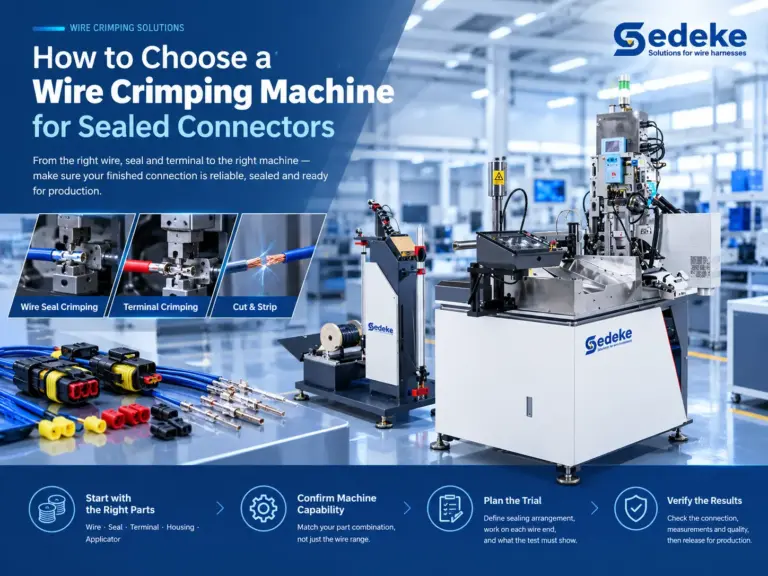


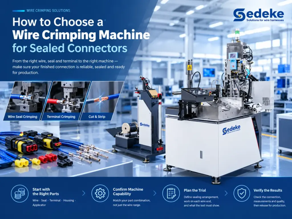
Wire crimping joins a conductor to a terminal. Use wire seal crimping when your connector specification calls for an individual seal around the wire insulation. The process adds seal handling and positioning to terminal preparation. For a connection without an individual wire seal, select the stripping and crimping process specified for that terminal system.
The purchasing decision starts with the finished connection. You need a compatible wire, seal, terminal, housing and applicator, followed by a machine that can process that combination. A terminal crimping machine’s wire range alone cannot answer whether it will handle your parts.
Before requesting a quotation, identify the sealing arrangement, define the work on each wire end and decide what the trial must demonstrate. The checks below turn those requirements into a useful equipment shortlist.
Identify the seal your connector actually uses
A single wire seal fits around the insulation of a populated wire entry. A cavity plug closes an unused connector cavity. Suppliers sometimes call both a waterproof plug, so use the component part number when discussing tooling or feeding.
There are also sealed connectors that use a different arrangement. TE Connectivity lists family or mat seals and radial seals alongside its automotive single wire seals and cavity plugs. A sealed connector therefore does not automatically require a machine that threads an individual seal onto each wire.
| Your connector requirement | Processing decision |
|---|---|
| An individual wire seal is specified | Include seal feeding, positioning and the specified terminal crimping operation |
| A mat seal or another sealing arrangement is specified | Follow that connector’s assembly instructions before selecting a wire preparation route |
| No wire-entry seal is required | Select stripping and crimping equipment for the specified wire and terminal |
| An unused cavity requires a plug | Treat cavity plugging as a connector assembly requirement; it is separate from crimping a populated wire |
For waterproof wire connectors, obtain the housing, terminal and seal references before selecting a seal insertion station. The component references determine the required operation; a general description such as “waterproof” leaves the sealing arrangement unclear.
Check the complete component combination
Conductor size and insulation outside diameter answer different questions. The conductor must fit the terminal’s wire barrel; the insulation must fit the specified seal. Two wires with the same conductor cross-section can have different insulation diameters.
The seal also has to work with the terminal and housing. TE’s MCON 1.2 connector guide, page 11, explains how the seal’s crimping zone and neck geometry affect retention without cutting the seal. It also describes compression between the seal and connector cavity. These interfaces explain why a seal that slides onto the wire is not yet a complete compatibility check.
Use this table with your component drawings. Record a match, mismatch or unresolved item in each row.
| Check | Information to compare | Decision before ordering equipment |
|---|---|---|
| Wire to seal | Wire specification, insulation material, permitted OD range and representative samples | Select the seal approved for that wire construction and diameter range |
| Seal to terminal | Seal and terminal part numbers, seal orientation and specified position | Establish the correct position and support geometry from the application specification |
| Terminal to applicator | Terminal part number, feed direction, applicator reference and crimp requirements | Confirm the tooling combination, rather than selecting by press force alone |
| Sealed terminal to housing | Housing reference, cavity arrangement and assembly instructions | Confirm that the prepared terminal can be installed and retained as specified |
| Finished lead to machine | Incoming wire condition and separate requirements for End A and End B | Assign every required operation to a station or downstream process |
Stop the machine selection if a required component match is unresolved. Increasing crimp force or changing seal position is not a substitute for choosing the specified parts.
Confirm the tooling and processing sequence
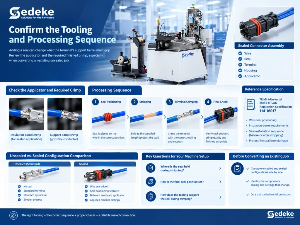
Adding a seal can change what the terminal’s support barrel must grip. Review the applicator and the required finished crimp together, especially when converting an existing unsealed job.
For example, TE’s Mini-Universal MATE-N-LOK application specification, 114-16017, gives specific wire-seal positioning and insulation-barrel requirements. Its sealed applications include a round insulation-barrel crimp requirement. That is a rule for the components covered by that document, not a universal crimp shape for every sealed terminal.
The same specification discusses installing the seal before or after stripping and protecting it from damage. Use the sequence approved for your connector system when reviewing the machine cycle. Ask where the seal is held during stripping, how its final position is set and how the tooling supports it during crimping.
For an existing production setup, compare the approved unsealed and sealed configurations side by side. Identify the components, tooling and settings that change before attempting a conversion.
Choose a wire crimping machine for your finished lead
At Sedeke, we offer seal insertion with stripping and terminal crimping, as well as an integrated route for leads that need different treatments at each end. Choose between them from your incoming material and finished lead drawing.
Prepared wire requiring seal insertion and crimping
Our TM-200SC and TM-200SCT combine seal insertion, stripping and terminal crimping. TM-200SC processes one wire at a time; TM-200SCT processes two. The seal feeding arrangement uses a vibrator and compressed air.
Consider this route when cutting is handled separately and you need to combine the remaining wire-end operations at one station. Processing two wires at a time describes the machine’s handling arrangement; it does not mean processing both ends of one wire simultaneously. Include the other end’s work in your wire harness manufacturing plan.
For jobs that mix conventional, multi-core and sealed wire ends, our stripping and crimping machine range helps you compare the available processing routes.
Reel-fed leads with a sealed crimp at one end and tinning at the other
Our ACC-107 combines cutting with seal insertion and terminal crimping on End A, and stripping, twisting and tinning on End B. This makes it a candidate when your finished lead requires that combination.
If both ends need sealed terminals, specify that requirement separately. The ACC-107 process described here finishes the second end by twisting and tinning.
ACC-107 includes seal presence detection, while terminal pressure inspection is an optional addition. For the trial, distinguish a missing seal from a seal that is present but misplaced or damaged. Each is a separate inspection question.
Make the trial answer your acceptance questions
Agree on the finished-part criteria before the demonstration. Bring the actual wire, terminal reel, seals and housing, together with the relevant drawings and application specifications. Otherwise, a successful demonstration on a different combination leaves your main purchasing question unanswered.
Use the following as a proposed trial plan. Your engineering and quality teams should select the sample quantities, defect conditions and acceptance limits for the application.
| Trial condition | Question to answer | Result to record |
|---|---|---|
| Approved reference parts | Does the setup produce the required strip, crimp and seal position? | Part references, recipe, measurements and first-piece decision |
| Missing-seal challenge | Does the specified detection function identify the missing seal? | Detection result, alarm, rejection action and retained record |
| Wrong seal or displaced seal | Which of these conditions can the installed inspection system distinguish? | Challenge condition, result and any missed or incorrectly rejected samples |
| Visibly damaged seal | Is there a clear inspection method and rejection criterion? | Defect description, inspection result and disposition |
| Changeover followed by a production run | Can the setup be restored and accepted parts produced consistently? | Time to approved first piece, accepted quantity and reasons for stops |
| Prepared terminal installed in its housing | Does the assembly meet the connector and finished-product requirements? | Required assembly, retention and system test results |
Have engineering approve the method for introducing challenge samples. Identify and segregate them so they cannot enter shipment, and keep the trial within the equipment’s operating instructions.
A force-monitor result answers a question about the measured crimping process. To establish coverage for a particular seal defect, demonstrate that defect with the installed monitoring system and record the response. Also check what happens after an alarm: detecting a defect and separating the affected part are different actions.
For output, record accepted parts over an agreed period that includes the relevant work. Note whether the figure covers loading, inspection, stops and changeovers. This gives you a more useful comparison than a cycle rate measured under a different operating boundary.
Keep the final sealing check in the assembly plan
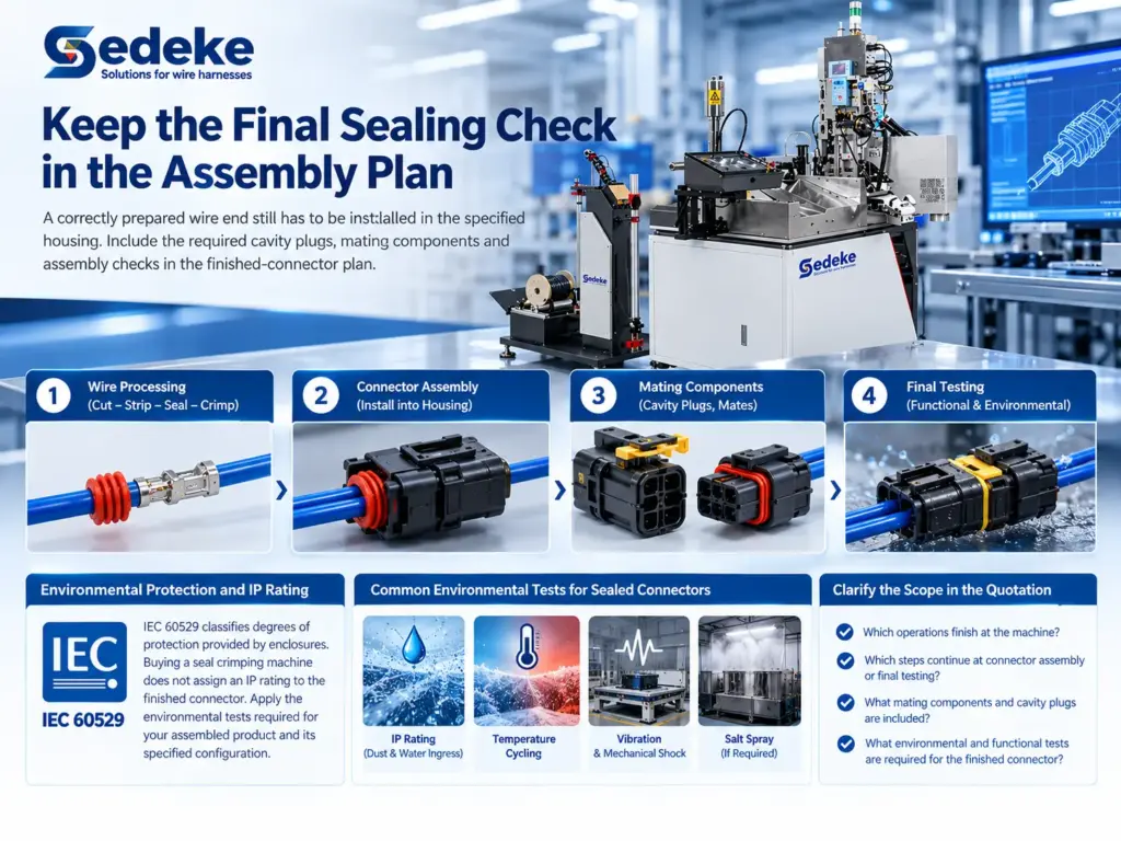
A correctly prepared wire end still has to be installed in the specified housing. Include the required cavity plugs, mating components and assembly checks in the finished-connector plan.
IEC 60529 classifies degrees of protection provided by enclosures. Buying a seal crimping machine does not assign an IP rating to the finished connector. Apply the environmental tests required for your assembled product and its specified configuration.
Keep this work visible in the quotation comparison. State which operations finish at the machine and which continue at connector assembly or final testing.
Frequently asked questions
Can I use the same machine for sealed and unsealed wires?
Ask for both processes to be included in the configuration proposal. Check seal-feed bypass, applicable tooling, saved settings and the changeover procedure. A suitable sealed-wire setup does not by itself establish the unsealed configuration.
Is a wire’s AWG size enough to select a seal?
No. Supply the insulation outside diameter and wire specification as well as conductor size. The selected seal also needs to match the terminal and housing system.
Can I keep my existing applicator when adding a seal?
Only if the applicator and tooling are suitable for the specified sealed terminal combination. Compare the required finished crimp and seal support with the applicator specification before scheduling the trial.
Does a seal presence sensor check seal damage too?
Presence, position and damage are different inspection tasks. Ask which tasks the installed system performs and demonstrate each claimed capability using controlled samples.
What should I send Sedeke first?
Start with your wire specification, a connector or finished-lead photo, and the operations needed at each end. Add terminal and seal part numbers if you have them. These details provide a practical starting point for discussing the machine route; drawings and acceptance criteria can follow for the application review.
Discuss your wire-end process with Sedeke
Send us the information you already have through the inquiry form on the relevant product page and ask for a configuration proposal for your lead. Include the other end’s treatment so the proposal addresses the complete job.