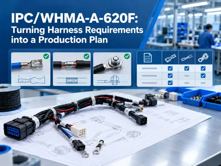


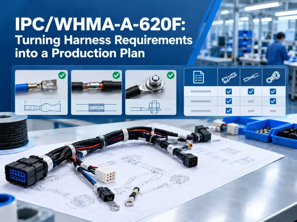
When a customer asks for a harness built to IPC/WHMA-A-620, get the applicable revision, product class and supporting documents clear before approving equipment or samples. Then assign each required check to a method, a responsible person and a record. That gives your supplier a defined job and your quality team a basis for accepting the result.
IPC/WHMA-A-620 covers manufacturing practices and acceptance requirements for cable and wire harness assemblies, including crimped, soldered and mechanically secured connections. The official standards overview currently lists Revision F. For a manufacturer buying cutting, stripping or crimping equipment, the practical question is how the proposed process will demonstrate the requirements specified for the actual assembly.
Settle the revision and class before approving the trial
Revision F is dated October 2025. A newer revision does not automatically replace the edition specified for your project; the user specifies the applicable revision. The class also requires agreement. The user has ultimate responsibility for identifying it; if the user has not established and documented a class, the manufacturer may do so.
The three classes describe end-use requirements:
- Class 1: the completed assembly’s function is the main requirement.
- Class 2: continued service and extended life matter, while uninterrupted operation is desirable rather than critical.
- Class 3: performance when needed is critical, with unacceptable downtime and potentially harsh conditions.
These points are set out in the official Revision F preview, sections 1.2–1.3. A label such as “medical” or “automotive” alone is not a sufficient basis for choosing a class.
Use the following responses when reviewing an inquiry:
| What the customer sends | Your next action | What should be resolved before acceptance testing |
|---|---|---|
| “Build to IPC-620” | Ask for the revision and class, together with the released drawing | A documented acceptance basis |
| A drawing naming an older revision and a class | Check whether a later purchase order or customer instruction changes that requirement | Which document governs this order |
| Revision F plus customer specifications | List the referenced documents and check for conflicting requirements | An agreed interpretation of any conflict |
| A supplier statement that a machine is “Class 3 ready” | Ask which assembly features and material combinations were tested | Relevant sample results against your requirements |
You can discuss machine feasibility while a document question is open. Keep the unresolved item visible in the quotation or trial plan rather than presenting the trial as an acceptance test with agreed criteria.
Build one requirement register that everyone can use
Create one row for each acceptance feature that affects the proposed process. Link the row to a document revision and a location within it. “Customer specification” is too vague when several revisions are circulating.
A useful working register contains:
Assembly part number → feature → source document and revision → criterion → method → responsible person → result record → unresolved issue.
For an exposed conductor, the feature might be strip length at End A. For a terminal, it might be crimp height for a particular wire–terminal–applicator combination. Keep the numerical criterion in the controlled register so the equipment supplier and inspector work from the same value.
| Decision or check | Input to collect | Evidence to request | If something is missing |
|---|---|---|---|
| Applicable requirements | Customer drawing, specified standard, class and additional instructions | Approved document list with revisions | Request clarification before calling the samples acceptable |
| Wire preparation | Wire construction, end details and required inspection criteria | Identified samples with dimensional and conductor-condition results | Resolve the missing feature or inspection method |
| Crimp geometry | Terminal part number, wire specification, applicator and applicable application instructions | Measurements tied to that combination | Resolve conflicting limits with the responsible engineering or quality team |
| Process monitoring | Approved reference samples, monitoring configuration and response plan | Results linked to the run and records of abnormal cycles | Establish the reference and response before relying on the monitor |
| Mechanical and electrical checks | Applicable methods, limits and sampling plan | Reports identifying the tested samples and results | Define the missing test requirement; do not invent a generic limit |
| Production handover | Accepted setup, open issues and change controls | Approved setup record and disposition of unresolved items | Keep unfinished approval work separate from permission to run production |
This is a practical planning template, not a list of additional requirements imposed by A-620.
Resolve conflicting documents before adjusting the machine
Consider an illustrative situation: the drawing names one terminal part number, but the application sheet supplied with the inquiry belongs to another. The supplier produces a sample and reports a satisfactory crimp height.
The missing step is to establish which terminal and application sheet govern the assembly. Ask the responsible customer contact to resolve the mismatch, record the decision, and then assess the sample against the correct combination. Changing the press setting to match an unrelated value would leave the documentation problem unresolved.
Use the same approach when two documents give apparently different limits. Record both references and check the project’s order of precedence. If the conflict remains, obtain an authorized clarification rather than choosing whichever value makes the existing sample pass.
Decide what each inspection method actually proves
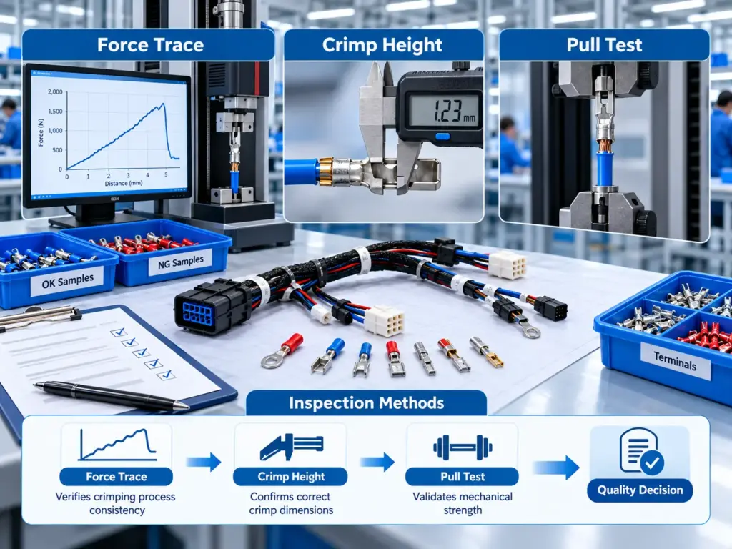
A force trace, a crimp-height result and a pull-test report answer different questions. Define their roles before comparing equipment quotations.
TE Connectivity’s technical paper on crimp-quality measurement explains that pull testing can miss some over-crimping conditions, while force monitoring alone does not establish that the crimp meets the original terminal design intent. It also describes limitations of height measurement on its own. The useful purchasing question is which combination of checks addresses your connection and its failure risks.
For each proposed check, ask:
- Which feature or defect is it intended to assess?
- Where does its acceptance criterion come from?
- How will the result identify the sample or production run?
- What happens when that result disagrees with another required check?
A normal force trace should not cancel an out-of-limit dimensional result. Likewise, a satisfactory measurement on a newly adjusted sample does not settle the disposition of earlier parts.
A-620 does not provide cross-section or X-ray acceptance criteria, and it does not prescribe a universal in-process or final inspection frequency. Its published scope makes those boundaries explicit. If your plan includes section analysis, identify the governing criteria separately. For inspection frequency, document the plan applicable to your process and customer requirements.
Match the equipment to the operation and required evidence
Choose the machine after identifying which operations it must perform and which checks sit outside it.
For a repeating wire family requiring cutting, stripping and single-end crimping, our ACC-101 cut-strip-crimp machine is a candidate for a combined processing route. Its published wire range is AWG 18–30, with a standard stripping range of 1–15 mm. Use those ranges to screen the application, then trial the actual wire, terminal and applicator against the agreed requirements.
For dimensional checking, our CHM-10 crimp-height measurer addresses crimp-height measurement. Keep any separately required pull tests, visual checks and completed-assembly tests in the plan.
In the equipment discussion, distinguish between a result the machine produces, a measurement taken with a separate instrument and a release decision made by your quality team. Ask how each record will be retained and connected to the relevant setup. A stored machine recipe alone does not demonstrate that the finished samples passed inspection.
For medical applications, our equipment trial and quality-plan guide develops the sample-testing stage in more detail, including different end preparations and shielded cable variants.

Close the trial with a result package
Before the demonstration, agree on the evidence you expect to receive. A useful package includes the following, with the level of detail set for your project:
- The tested combination: assembly and sample IDs, wire and terminal references, relevant material lots, machine, applicator and setup identification.
- The acceptance basis: the approved document list and a reference to each criterion used.
- The results: measurements and observations, including failed samples and any adjustment made during the trial.
- The disposition: which combinations were accepted, which need another trial, and who approved the next step.
Ask the supplier to preserve the difference between the initial setup and the accepted setup. Otherwise, a final photograph of a good part tells you little about the configuration that produced it.
If the trial fails, identify the affected operation, correct the cause and repeat the relevant checks. Keep the earlier samples and their results in the record. For an existing production line, follow your quality procedure to identify and disposition potentially affected output.
When changing the wire, terminal, tooling or approved recipe, review which parts of the evidence package are still applicable. This makes the next decision specific: repeat the checks affected by the change, with the extent determined by the responsible quality and engineering team.
Questions before you commit to a process
Does Class 3 require an automatic machine?
A-620F permits methods that produce assemblies meeting its acceptance requirements. It does not make automation a universal condition of Class 3. Select manual, semi-automatic or automatic processing around the approved method, production needs and demonstrated results.
Can we approve a machine using a sample made with a different terminal?
Use it to discuss the machine’s operation, but obtain relevant results for your intended combination before accepting its suitability. Record any difference in wire, terminal, applicator or preparation so the review does not overlook an untested condition.
Does a calibrated measuring tool make a sample acceptable?
Calibration addresses the measuring equipment. Sample acceptance also needs the applicable criterion, the correct measurement method and an actual result. Keep those items together in the inspection record.
Can an inspection photograph replace dimensional measurements?
Use photographs for the features they can meaningfully show. Where your inspection plan calls for a measurement, retain that result with the sample identity. A photograph without a defined method or reference should not be used to infer a numerical pass.
What should we send Sedeke to start equipment selection?
Send your cable or wire drawing, terminal part number and the operation that is causing difficulty. Include available samples and the specified A-620 revision and class if you have them. We can use those inputs to discuss a suitable processing route and the scope of a sample trial.
Plan the supplier trial around the decision you need to make
Before committing to equipment, identify the finished features it must control and the evidence your team needs to review. Resolve document conflicts early, keep each test result connected to its sample, and make unresolved items explicit before production approval.
Discuss your wire-processing application with Sedeke. Start with the drawing and end-connection details; we can help narrow the equipment route for your trial.