

medical cable assembly drawing tells you what the finished part must be. It does not tell you whether a cutter, stripper or crimper can hold those requirements across different reels, setups and operators. Before buying equipment or releasing a new process, turn the drawing into a trial plan: name each critical feature, its acceptance limit, how you will measure it, and what happens when a sample fails. Run the trial on the actual wire and terminal combination, including the variants that challenge feeding and stripping. This guide gives you a practical way to do that and shows where Sedeke equipment can fit. The finished-device manufacturer and its quality system still determine the applicable release requirements.

Start with the finished connection, then define the machine’s job
List every finished cable or harness variant you expect to make. For each one, collect the current drawing, bill of materials, wire and terminal specifications, approved inspection method, and required production records. Mark End A and End B separately. One end may need a crimped terminal; the other may need a different strip length or no terminal at all. A shielded cable may add jacket, braid and inner-conductor operations that a single-wire strip trial cannot represent.
Split the route into three boundaries:
If you are still mapping the full line, our wire harness assembly process guide covers the wider sequence. The trial below focuses on the operations and records you need to accept for this cable family.
| Boundary | Typical work | Who must define acceptance? |
|---|---|---|
| Wire preparation | Feed, cut, strip, partial strip or staged strip | Your approved drawing and process specification |
| Connection making | Crimp, solder or connector assembly as applicable | The wire, terminal and connector requirements together |
| Finished-assembly release | Visual, dimensional and electrical checks specified for the product | The finished-device manufacturer’s quality plan |
This prevents a common purchasing error: treating a machine’s cut-length specification as evidence that the completed assembly has passed electrical or mechanical release testing. Sedeke’s wire cutting and stripping range addresses the preparation boundary. If your approved route repeatedly combines cutting, stripping and a single-end crimp on fine wire, the ACC-101 cut-strip-crimp machine is a candidate to trial; its published processing range is AWG 18–30 and its published stripping range is 1–15 mm in standard configuration. Those catalogue ranges are a screening step, not an acceptance result for your cable and terminal.
Build an acceptance matrix before the supplier demonstration
Write one row per feature and failure mode. Use the drawing or approved component instruction for limits. The table below is a template; blank numerical limits are deliberate because there is no universal medical-cable strip length or pull-force value.
| Feature or risk | Trial input and sample | Measurement or observation | Acceptance source | If it fails |
|---|---|---|---|---|
| Finished cut length | Shortest and longest specified lengths | Measure finished wire to the drawing’s datum | Cable drawing | Check feed slip, straightening and length program; repeat the affected case |
| Strip length at each end | Every distinct End A/End B recipe | Measure exposed conductor and insulation position | Drawing and terminal instructions | Correct recipe, blade or feed setting; segregate affected output |
| Conductor damage | Smallest conductor and hardest-to-strip approved insulation | Inspect for nicked, severed or displaced strands using the approved method | Workmanship/inspection criteria | Stop stripping, adjust tooling and inspect samples made since the last accepted check |
| Crimp geometry | Each approved wire-terminal-applicator combination | Check crimp height and visual geometry; add pull-force or section checks if required | Terminal-maker data and quality plan | Stop that combination; inspect and disposition the affected batch |
| Shield and inner layers, if present | Each cable construction and strip stage | Check layer exposure, braid condition and insulation integrity | Cable/connector drawing | Treat as a separate recipe and trial; do not infer from a single-core wire run |
| Electrical result | Completed assembly, after connector insertion | Run the continuity, insulation-resistance or dielectric checks actually specified | Finished-product test plan | Quarantine failed assemblies and investigate the connection and test setup |
| Record link | Trial batch and normal work order | Retrieve material lot, recipe/tool revision, operator, checks and disposition | Your quality-system record requirements | Fix record capture before production release |
The point of the matrix is to make a demonstration falsifiable. “The machine ran the wire” is a feasibility observation. “These defined variants passed the approved checks, and the results can be traced to this setup and lot” is evidence your team can review.
Challenge the setup, not just the nominal sample
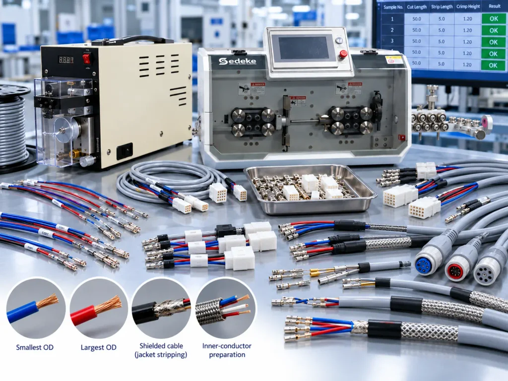
Start with a first-piece review for each wire-terminal combination. Then run enough consecutive pieces, at the intended speed and handling arrangement, for your quality team to judge repeatability. Include the smallest and largest approved conductor or cable outside diameters, different material lots where available, both end recipes, and the longest relevant feed length. If several operators or frequent changeovers are expected, repeat a first-piece check after a tool, reel or program change. Your sampling plan and pass criteria should be set by the responsible manufacturer; a fixed number copied from another product cannot establish suitability.
Consider an illustrative mixed family: a device uses a fine single-core signal wire with a terminal at End A, while a second variant uses a small shielded cable requiring staged jacket and inner-conductor preparation. A combined cut-strip-crimp route may be efficient for the stable single-core variant. The shielded variant needs its own cable-specific stripping trial and may require a separate station. Do not count the combined machine’s nominal pieces per hour as the capacity of the mixed family; include changeovers, first-piece approvals and downstream inspection in the output estimate.
Record each trial by material lot, equipment and tooling identity, program revision, settings, operator, timestamp and inspection result. The exact record fields follow your quality system, but the record must let you find which parts were made under a failed setup. A machine that stores a recipe does not by itself create full work-order traceability.
Separate process checks from final electrical testing
Place checks near the operation that can create the defect. A strip inspection detects conductor damage before termination. A crimp-height check can detect a change in the crimp setup before the wire enters a housing. Sedeke’s CHM-10 crimp-height measurer is one tool for that dimensional check. It does not measure pull force or prove the final electrical result; use the additional methods specified for your connection.
Continuity at the completed-assembly stage is useful for opens and wiring errors, but it cannot replace a defined check for nicked strands, crimp geometry or insulation damage. Add insulation-resistance or dielectric testing only where the finished-product test plan calls for it, using its prescribed method and limits. Keep the result linked to the correct unit or batch.
If a process check fails, stop the affected route, identify the last accepted check, segregate material produced since then, correct the cause, and re-run the first-piece and affected challenge cases before restart. The quality team determines disposition under its own procedure. A successful repeat on one new part does not automatically release the earlier batch.
Know which standards apply to the product and which guide workmanship
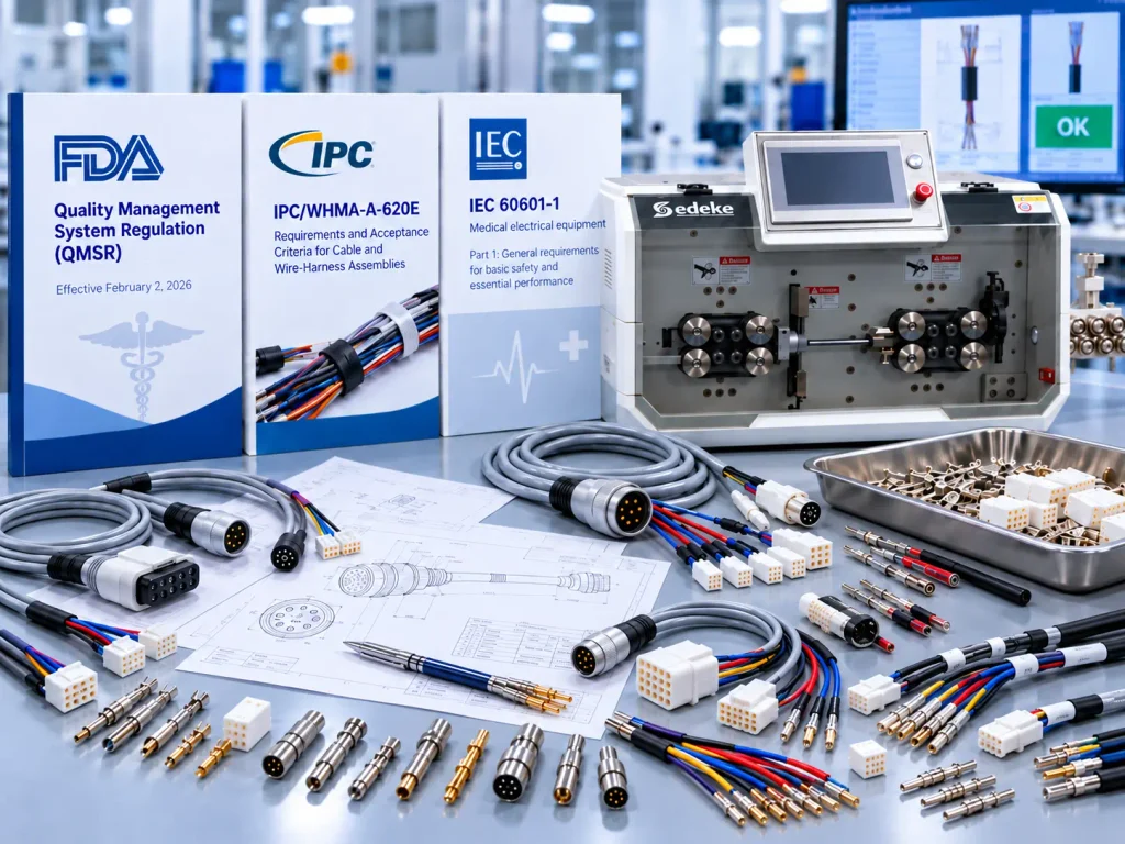
In the United States, the FDA’s Quality Management System Regulation took effect on February 2, 2026 and incorporates ISO 13485:2016 by reference. FDA describes its applicability in terms of finished-device manufacturers, including some accessory manufacturers. That scope does not mean every component supplier or every wire-processing machine has an FDA approval. The finished-device manufacturer determines supplier controls and records for the actual product.
IPC/WHMA-A-620E provides requirements and acceptance criteria for cable and wire-harness assemblies when the parties specify its use. It does not replace the device drawing or establish a universal medical cable specification. IEC 60601-1 covers general safety and essential performance of medical electrical equipment; whether it applies to a finished device is a product-level decision, not a blanket machine-selection rule.
Choose the equipment route from trial evidence
Use a separate preparation station when cable constructions, strip stages or changeovers differ substantially. Consider integrated cutting, stripping and crimping when the same approved wire-terminal family repeats and the trial confirms both output quality and practical throughput. Keep final assembly and its required electrical release checks in the route even when wire preparation is automated.
For an initial Sedeke review, send the wire or cable drawing and a short description of the finished end connections. If you already have samples, include them and identify the strip stages that currently cause scrap or rework. We can use that information to narrow the equipment route and discuss a trial against your specified checks. Your team retains the decision on product acceptance and production release.
FAQ
Is there one strip-length tolerance for all medical cable assemblies?
No. The drawing, terminal or connector instructions and approved inspection plan define the acceptable result for each connection. Measure both ends if their preparations differ.
Does a clean first piece qualify the process?
It shows the setup can make an acceptable piece. Your trial also needs to cover the approved material range, repeated production, relevant changeovers and the records required by your quality system.
Can continuity testing replace conductor and crimp inspection?
No. A circuit can pass continuity while a conductor strand is damaged or a crimp is outside its approved geometry. Apply the checks assigned to those failure modes.
Should shielded and unshielded cables share one trial?
Only where the same approved process and checks truly cover both. Different layers, strip stages or termination methods need separate challenge samples and may justify separate equipment routes.
What should I send Sedeke to start equipment selection?
Send the current wire or cable drawing, end-preparation details and any available samples. Add the target batch and changeover pattern if known. We can then discuss which preparation or crimping route is worth testing against your acceptance plan.
Final thoughts
Choose a machine only after you can show which finished features it controls, how each feature will be checked, and which variants challenge the setup. A short drawing-to-trial matrix makes the supplier discussion more useful and gives your quality team a clear basis for the next decision. Contact Sedeke with your drawing and samples to start that review.