

A wire harness assembly process is rarely automated as one uninterrupted line. You usually get a better result by automating stable, repeated operations first and keeping variable work manual or hybrid until the product family, fixtures and inspection method are ready.
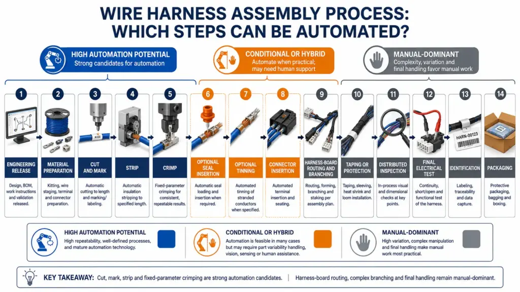
Cutting, marking and stripping are strong starting points. Crimping can also have high automation potential when the wire, terminal, tooling and process parameters are fixed. Seal insertion, tinning, connector loading and taping need a closer application review. Harness-board routing, complex branching and final handling often remain manual because the workpiece is flexible and the layout changes.
Before you request equipment, map the complete route. Then judge every step by material presentation, process control, changeover and accepted output. This gives you an automation scope that a supplier can evaluate against your real parts.
Map the complete wire harness assembly process
Your exact routing depends on the drawing, product and factory, but a high-level wire harness manufacturing process normally contains the following work:
- Release the drawing, bill of materials, routing and work instructions.
- Prepare wire, terminals, seals, connectors, tape and other components.
- Feed, measure, cut, identify and strip the wires.
- Prepare terminals and crimp the required wire ends.
- Insert individual wire seals when the design calls for them.
- Twist and tin stripped ends when the downstream connection requires tinning.
- Insert terminated wires into connector housings and build subassemblies.
- Route wires on a harness board, form branches and place clips or components.
- Apply tape, sleeving, heat shrink or other protection.
- Perform in-process checks and final visual and electrical testing.
- Complete identification, handling and packaging.
A machine may finish a cut, strip and crimp sequence, but the finished wire can still require housing insertion, routing, protection and testing. Research on automotive wiring-harness production describes large differences in automation between cutting, pre-assembly, complete assembly, electrical testing and packaging. It also notes that flexible cable shapes and component variety continue to constrain final assembly automation. See the open-access Springer review of automated wiring harness manufacturing.
You can use three practical classifications when you map the route:
| Classification | What it means | Operations to investigate |
|---|---|---|
| High automation potential | The material can be presented consistently, dimensions are programmable and the product family repeats | Cutting, identification, stripping and selected crimping |
| Conditional or hybrid | Suitability depends on components, orientation, fixtures, branches, access or changeover | Seal insertion, tinning, connector insertion, taping and selected inspection |
| Manual-dominant in many applications | Flexible geometry and product variation make handling difficult | Harness-board routing, complex branch formation, clip placement, rework and final handling |
These labels are a starting framework, not a universal rating. In practice, automated wire harness manufacturing is a collection of controlled steps, and you still need to test the actual application.
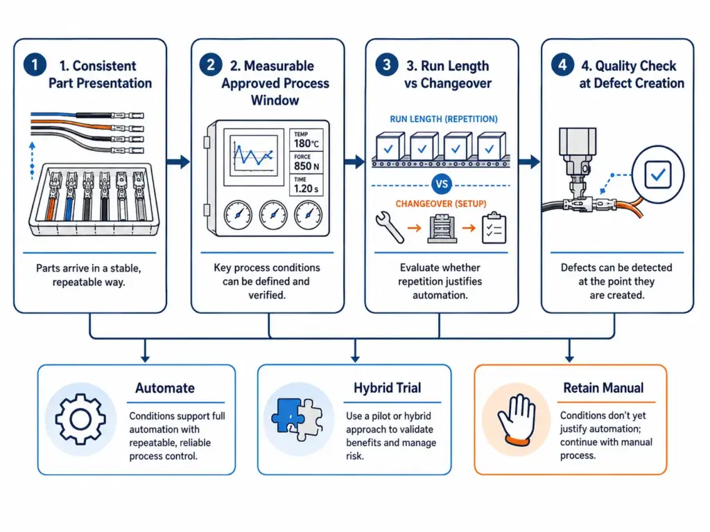
Use four questions before automating any step
Ask the same four questions for every operation in your current process.
Can you present the part consistently?
Wire can usually be fed from a reel or coil. Loose seals, terminals, connectors and flexible subassemblies each need a suitable presentation method. If a component arrives tangled, changes orientation or varies between batches, part handling may take more development than the processing operation itself.
Is the process window defined and measurable?
You need an approved target for cut length, strip length, conductor condition, crimp geometry, seal position, tinning condition or tape coverage. If the drawing and quality plan do not define the acceptable result, the machine supplier has no firm result to work toward.
Does the product run long enough after changeover?
Do not use annual volume alone. Review batch size, product mix, setup, tool changes, first-piece approval and material replenishment. A high gross speed can lose its value when the line changes products frequently.
Can you check quality where the defect is created?
Move the check close to the operation whenever possible. This helps you stop a process before a cutting, stripping, crimping or seal defect reaches final assembly. It also gives you better trial data during equipment evaluation.
If all four answers are clear, the step is ready for an automation trial. If one or two remain open, plan a hybrid route or validation project. If most answers are unknown, improve the process definition before you buy equipment.
Cut, mark and strip are strong automation candidates
Cutting and stripping suit automation because you can usually define the input material, finished length, strip dimensions and batch quantity in advance. Identification can also be added when the marking method and required position are stable.
Start by separating the wire families that behave similarly. Record conductor size, outside diameter, insulation material, cable construction, cut length, tolerance, strip length and any full, partial or intermediate stripping requirement. A simple single-core wire and a flexible multi-core cable may need different feeding, blades and validation even when their nominal size looks similar.
Check the complete material path as well. Pay attention to reel payoff, straightening, feed pressure, blade selection, scrap removal and the way finished wires leave the machine. An unstable feed or poor collection of long wires can simply move the bottleneck to another point.
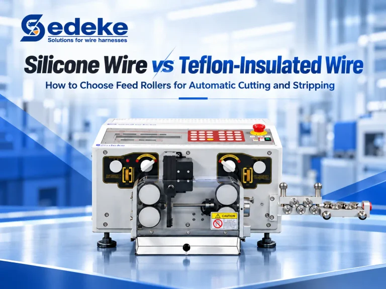
Sedeke’s current wire cutting and stripping equipment covers this process family. Use that category to review possible routes only after you have defined the material and finished dimensions. Do not select a model from nominal wire size alone.
Crimping has high potential when the matched system is stable
Crimping becomes a strong automation candidate when one approved combination of wire, terminal, applicator, tooling and parameters repeats. The connection is a matched system. The Springer review notes that the contact and wire must match. It also calls for a defined crimping tool and crimp parameters for that connection.
Your first decision is the process boundary. If wires already arrive cut and stripped, a separate terminal crimping equipment route may preserve flexibility. If one product family repeatedly needs feeding, cutting, stripping and crimping in sequence, integrated cut-strip-crimp systems may remove transfers between stations.
Whichever route you assess, define the quality gates before the trial. Your plan may include first-piece approval, crimp height, pull-force testing, conductor and insulation condition, terminal position and cross-section analysis where your specification requires it. Use the correct terminal drawing, applicator information and acceptance limits. A machine label such as fully automatic does not replace that process definition.
Seal insertion is a family-specific automation decision
Individual wire seals add another component that must be fed, oriented, opened and positioned without damage. Automation is more realistic when you have a stable wire, seal and terminal family with repeatable presentation. It becomes harder when seals vary frequently, cling together, arrive inconsistently or require different insertion and inspection methods.
Define the seal part number, wire range, orientation, position after insertion and rejection criteria. Confirm whether the seal is placed before stripping, before crimping or through another approved sequence in your process. Include any material handling or approved lubrication requirement from the component supplier.
Sedeke’s ACC-107 integrated route is one current example. Its published process combines cutting, stripping, waterproof-seal and pin handling, and terminal crimping on one end, with stripping, twisting and tinning on the other. That example proves the route exists. It does not confirm that your seal, terminal or wire is compatible, so you still need a sample and configuration review.
Tinning belongs only where the connection requires it
Do not add tinning because it appears in an integrated machine. Start with the downstream connection, customer drawing, component instructions and finished-part acceptance criteria. Some wire ends need tinning, while others need a crimped terminal, a ferrule or a different preparation.
If tinning is required, define End A and End B separately. Record the strip, twist, flux, solder, tinning length, cleanliness and inspection requirements that apply to the approved process. Then decide whether tinning belongs in the integrated route or at a separate station.
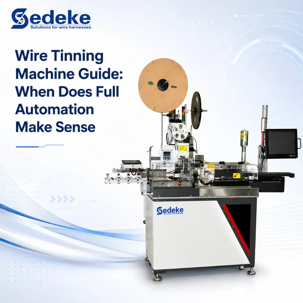
The wire tinning automation guide covers that decision in more detail. Keeping the connection requirement first prevents you from adding an unnecessary operation to every wire.
Taping is usually a hybrid automation decision
The word taping can describe several different jobs. You may need short point bundles, continuous spiral wrapping, a handheld tool for a branched harness, or only a machine that cuts tape to a preset length. These routes should not be treated as one automation level.
Use the harness geometry to select the route. Check:
- bundle diameter and stiffness;
- straight length available for wrapping;
- number and position of branches;
- connectors, clips and components that restrict access;
- tape material, width and roll format;
- required overlap or coverage;
- start and finish method;
- whether the harness is loose, supported or already on a board.
A straight, accessible section can be easier to wrap with a preset or automatic process. Short point bundles may need a different machine. Complex branches and restricted areas can favor handheld support or manual work. You may use more than one route on the same finished harness.
Sedeke’s current wire harness taping equipment includes separate point-bundling, wrapping, handheld and tape-preparation families. Compare them against your harness geometry and tape rather than asking for one machine to cover every taping task.
Put inspection where the defect can be created
Final electrical testing is necessary for many harnesses, but it should not be the first time you look for a process defect. Build checkpoints into the route:
| Process step | Possible check to define |
|---|---|
| Cutting and marking | Length, identification content and marking position |
| Stripping | Strip length, insulation condition and conductor damage |
| Crimping | First-piece approval, crimp measurement and mechanical checks required by the specification |
| Seal insertion | Seal presence, orientation, position and visible damage |
| Tinning | Prepared-end dimensions, coverage, wicking, residue and downstream fit as applicable |
| Taping | Coverage, overlap, start/finish condition and access to required components |
| Connector and board assembly | Cavity position, lock engagement, routing, branch dimensions and component placement |
| Finished harness | Continuity, open/short, pinout and visual checks required by the product plan |
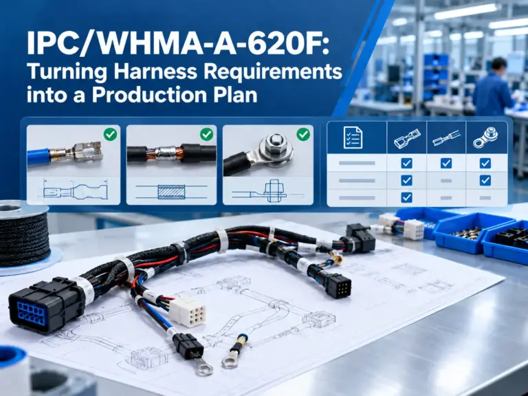
IPC/WHMA-A-620E addresses practices and acceptance for cable and wire harness assemblies, including crimped, mechanically secured and soldered interconnections. You must still confirm the applicable revision, product class, customer additions and order of precedence for your program. Mentioning the standard does not make a machine or process compliant.
Sedeke’s current crimp quality measurement tools include crimp-height, pull-force and terminal cross-section equipment. That category supports crimp-process checks. It should not be read as a complete final harness electrical-test system, which must be scoped separately.
Why routing and final assembly often remain manual or hybrid
An individual wire is relatively easy to feed through a controlled path. A partly assembled harness is different. It bends, twists, catches on fixtures and changes shape when another branch is moved. Connectors, clips, grommets and branch points add more orientations and handling tasks.
A factory can therefore automate much of its wire preparation while still using people for housing insertion, board routing, branch formation, clip placement and final handling. This is why automated wire harness assembly often remains hybrid after wire preparation. The Springer research identifies component count, component variation and flexible cable shape as obstacles to automation. Frequent component changes may also require tool changes that reduce equipment utilization and output.
Manual work is not automatically a process failure. It can be the more practical route when your mix changes often or the harness geometry is difficult to present. A hybrid cell can automate the repeatable operation while an operator handles loading, routing, exception work and inspection. Judge that choice by accepted output and process control, not by the percentage of labor removed.
Build an automation roadmap, not a machine shopping list
Start with one current product family and map every operation, queue, inspection and transfer. For each step, record:
- input and output condition;
- typical batch size and product mix;
- setup and first-piece approval time;
- operator tasks and touch time;
- common rejects, rework and stoppages;
- gross output and accepted output;
- upstream and downstream constraints;
- required changeovers, tools and fixtures.
Then prioritize the bottleneck that also has stable inputs and clear acceptance criteria. The slowest manual step is not always the best first project. If it handles a different harness every few minutes, automation can spend more time changing over than producing.
Use a simple internal calculation during trials:
Available run time = staffed shift time - setup - first-piece approval - replenishment - planned cleaning - downtime
Accepted output = gross output - rejects - parts held for rework or further inspection
Compare the current and proposed routes with the same product family, shift boundary and acceptance rules. Ask the supplier to state the sample, material, operations and test conditions behind any output figure. This gives you a better basis than comparing maximum machine speed.
What to send Sedeke for an automation review and quotation
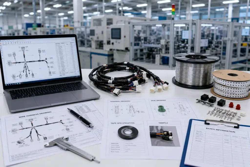
A useful inquiry describes the application instead of giving only a machine name. Prepare the following package:
- Your current process flow and the bottleneck you want to change.
- Representative wire, terminal, seal, connector, tape and finished-harness samples.
- Wire construction, conductor size, outside diameter and insulation material.
- Drawings and requirements for End A and End B.
- Cut, strip, crimp, seal, tinning, taping and identification requirements that apply.
- Terminal and seal part numbers, drawings and tooling information.
- Typical batch size, product mix, staffed shifts and changeover frequency.
- First-piece, in-process and final acceptance checks.
- Current gross output, rejects, rework and target accepted output.
- Available utilities, floor-space limits and upstream/downstream interfaces.
Send this package through the Sedeke contact page and ask for an automation-scope review and current quotation. Sedeke can compare separate and integrated process routes against the supplied application. Keep unknown values marked as open so they can be tested or confirmed rather than silently assumed.
Frequently asked questions
Which wire harness process should you automate first?
Start with a repeated bottleneck that has consistent material presentation, a defined process window and measurable acceptance checks. Cutting and stripping are common candidates, but your own flow and product mix should decide the first project.
Can the entire wire harness assembly process be fully automated?
Some product families can integrate several preparation steps, but complete automation is not a safe default. Flexible routing, branches, connectors, clips, changeovers and exception handling can keep final assembly manual or hybrid.
Can one machine cut, strip and crimp wire?
Yes, integrated cut-strip-crimp routes exist. You still need to match the wire, terminal, applicator, tooling and acceptance criteria, then validate the route with representative samples.
How should you measure automation output?
Track accepted parts released to the next operation after setup, approval, replenishment, downtime, rejects and rework. Gross machine speed is useful only when the test conditions match your application.
How should you compare two automation quotations?
Align the process scope first. Compare included operations, sample results, accepted output under stated conditions, changeover, inspection, fixtures, utilities, maintenance, support and the work that remains outside the machine.
Final thoughts
Wire harness automation works best when you treat it as a sequence of process decisions. Automate the stable, measurable work first. Keep flexible operations manual or hybrid until their presentation, fixtures and acceptance checks support a stronger case.
When you have mapped the route, send Sedeke your representative materials, end requirements, batch and changeover data, quality checks and target accepted output. That information gives the technical team a sound basis for reviewing the application and preparing a current quotation.