

A wire tinning machine makes sense when you have a repeated, approved wire-end process and enough work to benefit from combining its separate steps. It does not make sense simply because a fully automatic line is available.
Before you compare machines, confirm that the downstream connection requires a tinned wire end. Then define what must happen to each end of the wire, how you will judge acceptable output, and how often the product changes. Those details tell you whether you need single-end tinning, double-end tinning, a crimp-and-tin process, or a separate tinning station.
The steps below help you make that decision and prepare a quotation request a supplier can evaluate.
What a wire tinning machine actually automates
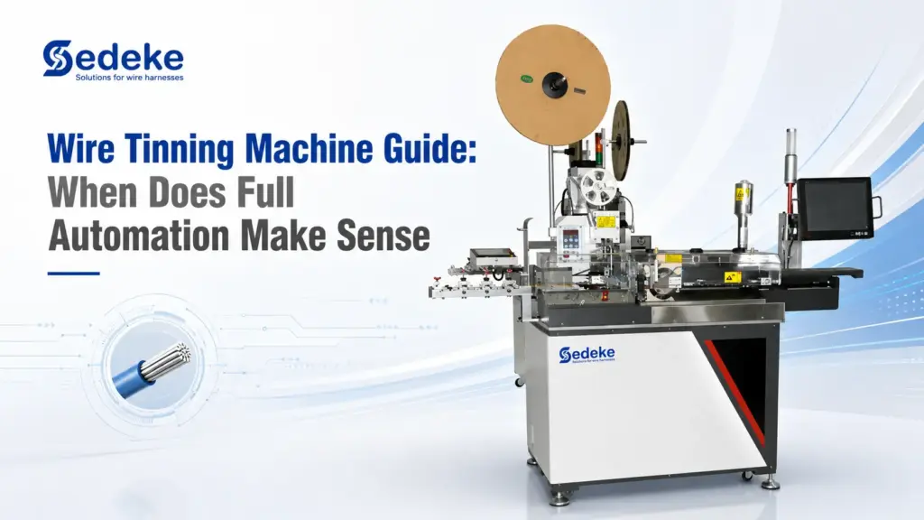
Wire-end tinning applies solder to the prepared end of a stranded conductor. It is different from soldering that conductor to a terminal, connector or circuit board. The distinction matters because some equipment is described as a wire soldering machine even when its main job is end preparation through tin dipping.
Depending on the configuration, an automatic wire tinning process may include:
- Feeding the wire.
- Measuring and cutting it.
- Stripping one or both ends.
- Twisting the exposed strands when required.
- Applying flux.
- Tinning one or both wire ends.
- Cooling and inspecting the finished end.
Not every machine includes every step. One line may tin one end and leave the other stripped. Another may tin both ends. A third may crimp a terminal on one end and tin the other. You need to specify the complete route instead of relying on a broad label such as automatic wire soldering machine.
Check the downstream connection before you automate
Do not add tinning by default. Start with the drawing, the connector manufacturer’s instructions, your customer’s specification and the acceptance requirements for the finished harness.
For example, Phoenix Contact documents why tinned stranded conductors can become unsuitable in some screw-style terminal blocks. Compression and thermal cycling can affect the clamped tinned end. That example is not a universal ban on wire tinning. It shows why the connection method must control your process choice.
Ask these questions first:
- Where will the prepared wire end be connected?
- Does the terminal or connector supplier permit or require a tinned end?
- Does the customer drawing define the solder alloy, flux, tinning length or inspection method?
- Will the tinned section be clamped, crimped, soldered or inserted into another component?
- Which defects cause rejection in your application?
If these answers are still open, you are not ready to select a fully automatic line. You are ready to validate the termination requirement.
When full automation makes sense
Consider full automation when the work is stable enough for one integrated route to keep producing accepted parts. Look for the following conditions.
Your product families repeat
You run the same wire and end-process combinations often enough that setup and first-piece approval do not consume most of the available production time. There is no universal minimum batch size. Your own changeover time and accepted output determine the threshold.
Several required steps are currently separated
If your approved route repeatedly moves through cutting, stripping, twisting, fluxing and tinning stations, integration can remove some handling between those operations. The benefit must be measured in the complete route, not assumed from the machine’s cycle speed.
The process window is already defined
You know the required strip length, twist condition, flux and solder system, tinning length, end orientation and inspection criteria. Automation is easier to assess when the target is an approved sample rather than a vague request for a “better” tinned end.
You can support the process around the machine
The line still needs material replenishment, solder-pot care, cleaning, waste handling, inspection, preventive maintenance and suitable fume control. If those tasks are not planned, an integrated machine can simply move the bottleneck.
You measure accepted output
You compare good parts delivered to the next process instead of relying on gross pieces per hour. This protects you from choosing a machine based on a headline figure that does not reflect your wire, length, end treatment, changeover pattern or acceptance criteria.
When a separate or semi-automatic process is the better fit
A less integrated route can be the better production decision when flexibility matters more than continuous output.
Keep a separate or semi-automatic tinning process on the table when:
- you are producing prototypes or small, irregular batches;
- wire types and end treatments change frequently;
- only a small share of cut and stripped wires require tinning;
- the customer specification is still changing;
- operators need to route work to different downstream processes;
- your current cutting and stripping equipment still has useful capacity;
- you have not yet established a repeatable tinning and inspection window.
Compare the routes by accepted cost, process control and the flexibility your work requires. The most automated option does not automatically win that comparison.
Choose the process boundary before the model
Once the connection requirement is clear, define End A and End B separately. This prevents you from requesting a machine with the wrong set of operations.
| Required route | What you should specify | Sedeke route example |
|---|---|---|
| Single-end tinning | Which end is tinned, what happens to the opposite end, and whether twisting is required | ACC-105 combines cutting, stripping, twisting and single-end tinning |
| Single- or double-end tinning | Whether one or both ends are tinned and whether the end specifications are identical | ACC-308 supports cutting, stripping, twisting and single- or double-end tinning routes |
| Crimp one end and tin the other | Terminal and applicator requirements for the crimped end, plus the complete tinning requirement for the other end | ACC-106 combines single-end crimping with single-end tinning and can process one to five wires at a time depending on the material |
These examples help you identify a process family. They do not confirm that a specific wire, terminal or finished-part requirement is compatible. That still needs sample evaluation and configuration review.
Compare accepted output, not headline speed
Machine specifications are useful for screening, but your production decision should use an accepted-output model built from your own work.
Start with:
Available run time = staffed shift time - changeover - first-piece approval - replenishment - planned cleaning - downtime
Then calculate:
Accepted output = gross output - rejects - parts held for rework or further inspection
Finally compare the current and proposed routes:
Accepted cost per part = total route cost for the period / accepted parts released to the next process
Use the same wire family, shift length, staffing boundary and acceptance rules on both sides. Include the time spent moving work between stations in your current route. For the proposed route, include setup, material loading, solder and flux care, inspection, maintenance and expected downtime.
You should also run at least three scenarios:
- a stable repeat order;
- a normal mixed-production period;
- a difficult period with frequent changeovers or a sensitive wire.
This gives you a useful comparison without inventing a universal payback period. If a supplier quotes only maximum speed, ask for the test conditions and request a sample run with your material.
Define tinning quality before you request a quote
Your approved sample, drawing and applicable workmanship requirement should define quality. If the acceptance target is unclear, neither you nor the supplier can judge a sample run properly.
Your inspection plan may need to address:
- strip length and insulation condition;
- cut, nicked or missing conductor strands;
- strand twist, if the process requires it;
- tinning length and boundary;
- solder wetting and coverage against the approved requirement;
- solder wicking beyond the permitted area;
- excess solder buildup or an end shape that interferes with the next operation;
- flux residue and cleanliness requirements;
- mechanical, electrical or downstream assembly tests required by the product.
IPC/WHMA-A-620 covers requirements and acceptance for cable and wire harness assemblies, including soldered interconnections. You still need to identify the version, product class, customer amendments and order of precedence that apply to your work. Do not write “IPC compliant” in a machine requirement unless your actual process and acceptance plan support that statement.
Include facility and maintenance requirements
An integrated tinning line brings heated solder, flux and regular process care onto the production floor. Review those supporting conditions before you compare floor plans or quotations.
Confirm:
- the approved solder and flux materials;
- replenishment, temperature control and cleaning procedures;
- local exhaust and site EHS requirements;
- operator access for setup, inspection and maintenance;
- scrap, dross and residue handling;
- compressed air, electrical supply and available floor space;
- preventive-maintenance responsibility and spare-part planning.
OSHA’s general requirements include ventilation and fume-control provisions for specified heated-metal and flux work. They are not a complete compliance checklist for your tinning line. Your materials, equipment documentation, local law and site EHS assessment determine the controls you need.
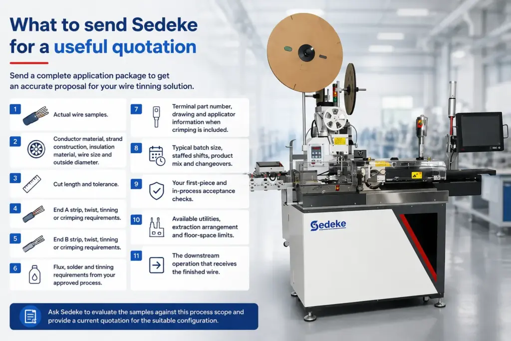
What to send Sedeke for a useful quotation
A request such as “I need an automatic tinning machine” leaves too many technical and commercial variables open. You will get a more useful proposal when you send an application package that defines the product and the production pattern.
Include:
- Actual wire samples.
- Conductor material, strand construction, insulation material, wire size and outside diameter.
- Cut length and tolerance.
- End A strip, twist, tinning or crimping requirements.
- End B strip, twist, tinning or crimping requirements.
- Flux, solder and tinning requirements from your approved process.
- Terminal part number, drawing and applicator information when crimping is included.
- Typical batch size, staffed shifts, product mix and changeovers.
- Your first-piece and in-process acceptance checks.
- Available utilities, extraction arrangement and floor-space limits.
- The downstream operation that receives the finished wire.
Ask Sedeke to evaluate the samples against this process scope and provide a current quotation for the suitable configuration. If an item is still undecided, mark it as open rather than replacing it with an assumed value.
Frequently asked questions
What is the difference between wire tinning and wire soldering?
Wire tinning prepares a stripped conductor by applying solder to its end. Wire soldering usually refers to making a connection between the conductor and a terminal, connector or board. Machine names do not always preserve that distinction, so define the required operations in your quotation.
When is an automatic wire tinning machine worth considering?
Consider it when the approved product family repeats, several preparation steps can be integrated, the process window is defined, and your accepted-output calculation remains favorable after changeover, inspection, rejects and downtime.
Is full automation always more consistent than manual tinning?
Do not assume that from the automation label. Consistency depends on a controlled process, suitable material, correct setup, maintenance and an inspection plan. Validate the proposed route with your samples and acceptance criteria.
Do I need single-end or double-end tinning?
Follow the required connection at each end. If only one end needs tinning, specify what happens to the other end. If both ends need tinning, state whether their strip, twist and tinning requirements are the same.
Can one machine crimp one end and tin the other?
Yes, that process route exists. Sedeke’s ACC-106 is one verified example. You still need to confirm the wire, terminal, applicator, material and finished-part requirements through sample review.
Final thoughts
Full automation makes sense when it fits an approved connection, a repeatable product family and a measurable production case. If any of those foundations are missing, validate them before you select the machine.
When your process is defined, send Sedeke the actual wire samples, End A and End B requirements, production pattern and acceptance checks. Sedeke can then review the application and provide a current quotation for the appropriate single-end, double-end or crimp-and-tin route.