

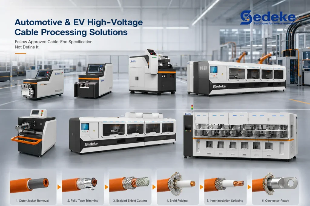
An automotive high-voltage cable end is built in layers. During EV wire harness manufacturing, you may need to remove the outer jacket, trim foil or tape, cut the braided shield, fold the braid and strip the inner insulation before connector assembly. The correct sequence depends on the cable construction and the connector work instruction.
This guide covers factory preparation of disconnected automotive and EV braided-shield cable. It does not cover field termination of medium- or high-voltage power-distribution cable, energized service work, shield-system design or grounding practice. Those applications use different cable structures, instructions and safety controls.
Sedeke’s automotive cable-processing equipment includes dedicated shield-cutting and folding equipment as well as machines that combine several preparation steps. The machine should follow your approved cable-end specification. It should not define that specification for you.
Start with the cable and termination specification
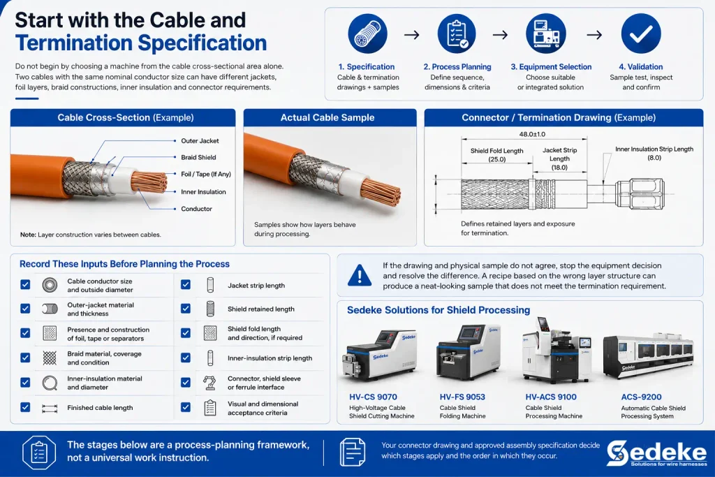
Do not begin by choosing a machine from the cable cross-sectional area alone. Two cables with the same nominal conductor size can have different jackets, foil layers, braid constructions, inner insulation and connector requirements.
Start with a cable drawing and an actual sample. The drawing tells you what the cable is supposed to contain, while the sample shows how the layers behave during cutting, stripping and folding. You also need the connector or termination drawing because it defines which layers remain and how much of each layer must be exposed.
Record these inputs before planning the process:
- cable conductor size and outside diameter;
- outer-jacket material and thickness;
- presence and construction of foil, tape or separators;
- braid material, coverage and condition;
- inner-insulation material and diameter;
- finished cable length;
- jacket strip length;
- shield retained length;
- shield fold length and direction, if required;
- inner-insulation strip length;
- connector, shield sleeve or ferrule interface;
- visual and dimensional acceptance criteria.
If the drawing and physical sample do not agree, stop the equipment decision and resolve the difference. A recipe based on the wrong layer structure can produce a neat-looking sample that does not meet the termination requirement.
The stages below are a process-planning framework, not a universal work instruction. Your connector drawing and approved assembly specification decide which stages apply and the order in which they occur.
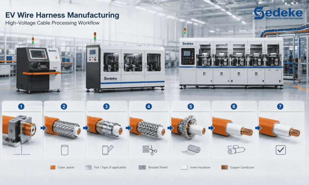
Typical stage 1: Cut and stabilize the cable
The finished cable length should be established before shield processing. The cable end also needs a repeatable position, because every later dimension is measured from a physical datum.
Check whether the cut end is square enough for the next operation and whether the cable remains round when clamped. A soft or flexible cable may flatten under excessive force. A curved cable can also enter the stripping or shield-cutting station at an angle. Either condition changes the relationship between the tool and the cable layers.
Your setup should hold the cable firmly enough to prevent movement without deforming it. If the cable arrives from an upstream cutting operation, confirm its discharge orientation and the amount of straightening or manual positioning needed before the first strip.
Typical stage 2: Strip the outer jacket
The outer jacket must be removed to the specified length while leaving the shielding layer in a usable condition. The tool should cut deeply enough to release the jacket but not so deeply that it scores the braid or the layer beneath it.
After stripping, inspect more than the exposed length. Look for braid strands pulled out with the jacket, an incomplete cut around the circumference, torn jacket edges or a cable that moved during removal. If the jacket is difficult to release, changing force alone may make the damage worse. You may need to review blade geometry, cut depth, cable positioning or the material’s response to the process.
The HV-ACS 9100 cable shield processing machine is an available Sedeke configuration for combined outer-insulation stripping and shield cutting. Confirm whether your process also requires a separate downstream inner-insulation operation. The cable still has to be tested against the selected configuration’s application range.
Typical stage 3: Remove foil or a separator only when required
Not every shielded cable has the same layer between its outer jacket and braid. Some constructions include foil, tape, a separator or more than one of these. Others expose the braid directly after jacket removal.
Treat this as a conditional step. Confirm what must be removed, what must remain and the retained length. Do not assume that a foil layer can be handled as part of the braid-cutting operation. The materials can behave differently, and a tool that controls copper braid may not control a thin foil edge in the same way.
After the operation, check that the required material has been removed cleanly and that the braid has not been pulled out of position. If any foil or separator must remain, verify its length against the approved sample or drawing rather than relying on visual symmetry.
Connector-specific sequence gate
Pause before shield trimming or fold-back and check the connector work instruction. Depending on the connector design, an inner ferrule, shield sleeve, strain-relief component, seal or filler/dielectric operation may need to occur before or between the shield operations.
Published equipment guidance shows why this gate matters. TE Connectivity describes jacket, foil, braid and inner-insulation processing, with braid fold-back tailored to the termination specification. Your connector work instruction may place a ferrule, shield sleeve, strain-relief component or seal between these cable-preparation operations.
These examples do not define the sequence for your product. They show why you must lock the connector-specific order before selecting tools, fixtures or an integrated machine recipe.
Typical stage 4: Cut the braided shield to length
Shield cutting establishes the braid length required for the next termination step. The cut should be even around the cable, and the process must avoid unacceptable contact with the inner insulation.
First define the retained length and its datum. Then inspect the full circumference after cutting. A single viewing angle can hide long strands, partially cut braid or damage on the far side of the cable. Loose strands also need to remain controlled so they do not move into the inner-insulation stripping area.
For a dedicated operation, Sedeke’s HV-CS 9070 high-voltage cable shield cutting machine is designed around controlled positioning and protection of the layer beneath the braid. Actual suitability still depends on your cable sample, retained shield length and acceptance standard.
Do not derive the shield-cutting tolerance from a general machine specification. Use the cable-end or connector specification, then confirm the result through sample processing.
Typical stage 5: Fold back the braid when the termination requires it
Some connector systems require the retained braid to be folded back over the jacket or formed for a shield-contact component. Other terminations use a cut braid without this step. Folding is therefore not a universal requirement.
When folding is required, define the fold direction, finished length and acceptable strand arrangement. Check that the braid forms an even layer rather than gathering on one side. Watch for loose strands, an irregular fold edge or a fold that changes when the cable is moved to the next station.
You can perform folding at a separate station or include it in a combined process. Sedeke lists the HV-FS 9053 as a dedicated semi-automatic folding route. Its HV-ACS 9300 high-voltage cable processing machine combines outer and inner insulation stripping with braided-shield cutting and folding.
An integrated sequence can reduce transfers between separate operations, but integration does not remove the need to inspect the braid. You still need to confirm that the folded shield holds its required geometry after the cable leaves the machine.
Typical stage 6: Strip the inner insulation
Once the shield has the required form, the inner insulation can be stripped to expose the conductor for the next operation. The exact position of this step may vary with the cable and equipment sequence, so follow the approved process rather than treating this order as universal.
Set the strip length from the termination drawing. Then check the conductor and the remaining insulation edge. Reject or investigate results with damaged conductor strands, incomplete insulation removal, an unacceptable insulation edge or loose shield strands near the exposed conductor.
The cable may be more difficult to position after the braid has been cut or folded. Make sure the shield does not change the cable’s seating in the stripping fixture. If the process is integrated, confirm that the same datum is maintained across the relevant operations. If it uses separate stations, define how the operator locates the cable at each one.
Typical stage 7: Inspect the prepared cable end
A completed machine cycle is not the same as an accepted cable end. Inspection should cover the dimensions and condition needed for connector assembly.
Build the check around your drawing and approved sample. Depending on the termination, this may include:
- outer-jacket strip length;
- retained foil or separator length, if applicable;
- shield cut length and circumferential uniformity;
- folded-shield length and strand arrangement, if applicable;
- inner-insulation strip length;
- conductor condition;
- condition of the inner insulation after shield cutting;
- absence of uncontrolled braid strands;
- final geometry needed by the connector or shield-contact component.
Do not rely on one good first sample. Check the start of a batch, repeat production and a representative changeover. Include the cable variants that are hardest to process, not only the most stable construction.
When you approve a recipe, record the cable identity, tooling, relevant settings, finished dimensions and inspection result. If cable supply, jacket behavior or braid construction changes, verify the recipe again before assuming the previous result will repeat.
Separate workstations or integrated processing?
Separate stations can make sense when you need only one shield operation, when products follow different process routes or when you want to add one controlled step to an existing line. A dedicated cutter and folder also let you evaluate each operation independently. You pay for that flexibility with more transfers, repeated positioning and more work in process.
Integrated equipment can combine several steps around one cable position and recipe. It works best when a repeated cable family follows a stable sequence. The cable construction, process order and tooling must all fit that route, so a machine with more functions is not automatically a better match.
Compare the two routes using accepted output rather than the fastest individual cycle. Include:
- loading and positioning time;
- processing time for every required layer;
- transfer time between stations;
- tool or recipe changeover;
- inspection and rework;
- operator handling;
- traceability requirements;
- the number of accepted cable ends delivered to connector assembly.
If your product mix includes both cut-only and cut-plus-fold terminations, show that mix during application review. It may support a flexible integrated route, separate equipment or more than one production cell. The decision cannot be made from the longest cable or largest cross-sectional area alone.
What to send Sedeke for an application review and quotation
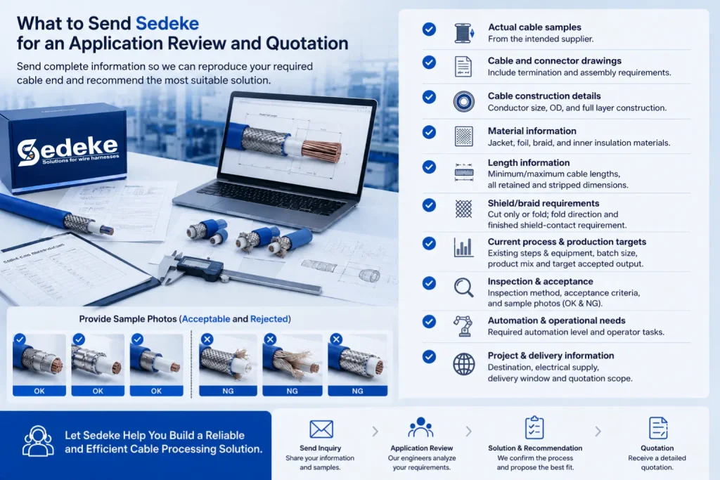
Send enough information to reproduce the required cable end. A useful inquiry package includes:
- actual cable samples from the intended supplier;
- cable and connector drawings;
- conductor size, cable outside diameter and full layer construction;
- jacket, foil, braid and inner-insulation materials where known;
- minimum and maximum cable lengths;
- all retained and stripped dimensions;
- whether the braid is cut only or also folded;
- fold direction and finished shield-contact requirement;
- current process steps and equipment, if any;
- batch size, product mix and target accepted output;
- inspection method and acceptance criteria;
- sample photos showing acceptable and rejected cable ends;
- required automation level and operator tasks;
- destination, electrical supply, required delivery window and quotation scope.
Ask Sedeke to review the samples, confirm the feasible process sequence and identify whether a dedicated or integrated route fits the application. Request a current configuration and quotation only after the required cable-end result has been defined. You can submit the package through the Sedeke inquiry page.
FAQ
What is cable shield processing?
Cable shield processing prepares the shielding layers at a cable end for the specified termination. It may include jacket stripping, foil or separator handling, braid cutting, braid folding and inner-insulation stripping. The exact steps depend on the cable and connector.
Is shield folding always required?
No. Fold the braid only when the termination specification requires that geometry. Some cable ends need a controlled retained braid without a fold, while others use a folded shield for a contact component.
Can shield cutting damage the inner insulation?
Yes, an unsuitable cut depth, position, tool or cable setup can contact the layer beneath the braid. Define the retained length and inspect the full circumference of the inner insulation after sample processing.
Should you use separate stations or one integrated machine?
Use the route that matches your product mix, process sequence, changeover needs, handling and accepted output. Separate stations offer operation-level flexibility. Integrated equipment reduces transfers when the cable family and sequence fit one combined process.
What should you send for a machine quotation?
Send actual cable samples, cable and connector drawings, layer materials, processing dimensions, required cut or fold geometry, batch mix, output target and acceptance criteria. A cable size by itself is not enough for a reliable equipment review.
Final thoughts
Automotive high-voltage cable shield processing should follow the cable and connector specification. Confirm the layers first, pass the connector-specific sequence gate, define which material remains at each stage, and inspect the prepared end before connector assembly.
Once the required result is clear, you can compare dedicated shield cutting and folding with an integrated processing route. Send Sedeke the physical samples, drawings and acceptance requirements so the recommendation and quotation are based on the cable you will actually run.